PAGE 2
A Net2 plus can connect to the Net2 PC using either an un-shielded RJ45 patch cable or an RS485 data line. This
greatly increases the number of installation options available to the installer.
One Net2 plus can also be used as the TCP/IP interface for an RS485 daisy chain of Net2 plus and Net2 classic units.
When used with a TCP/IP connection, it must rst be detected using the Net2 Server Conguration Utility as dened
later in this instruction.
When used with an RS485 data line, on-board termination resistors can be put in circuit with a simple slide switch.
Ensure that units installed in the middle of the data line have this switch turned OFF.
A dedicated Intruder Alarm connection is provided.
Overview
The TCP/IP interface allows an RS485 data line to be controlled by the Net2 Server running across a LAN network.
An RS485 data line has a 1000 yds maximum. This distance can be increased with the use of Paxton high speed
repeaters or by using shorter independant data lines using multiple LAN connections controlled from the same PC.
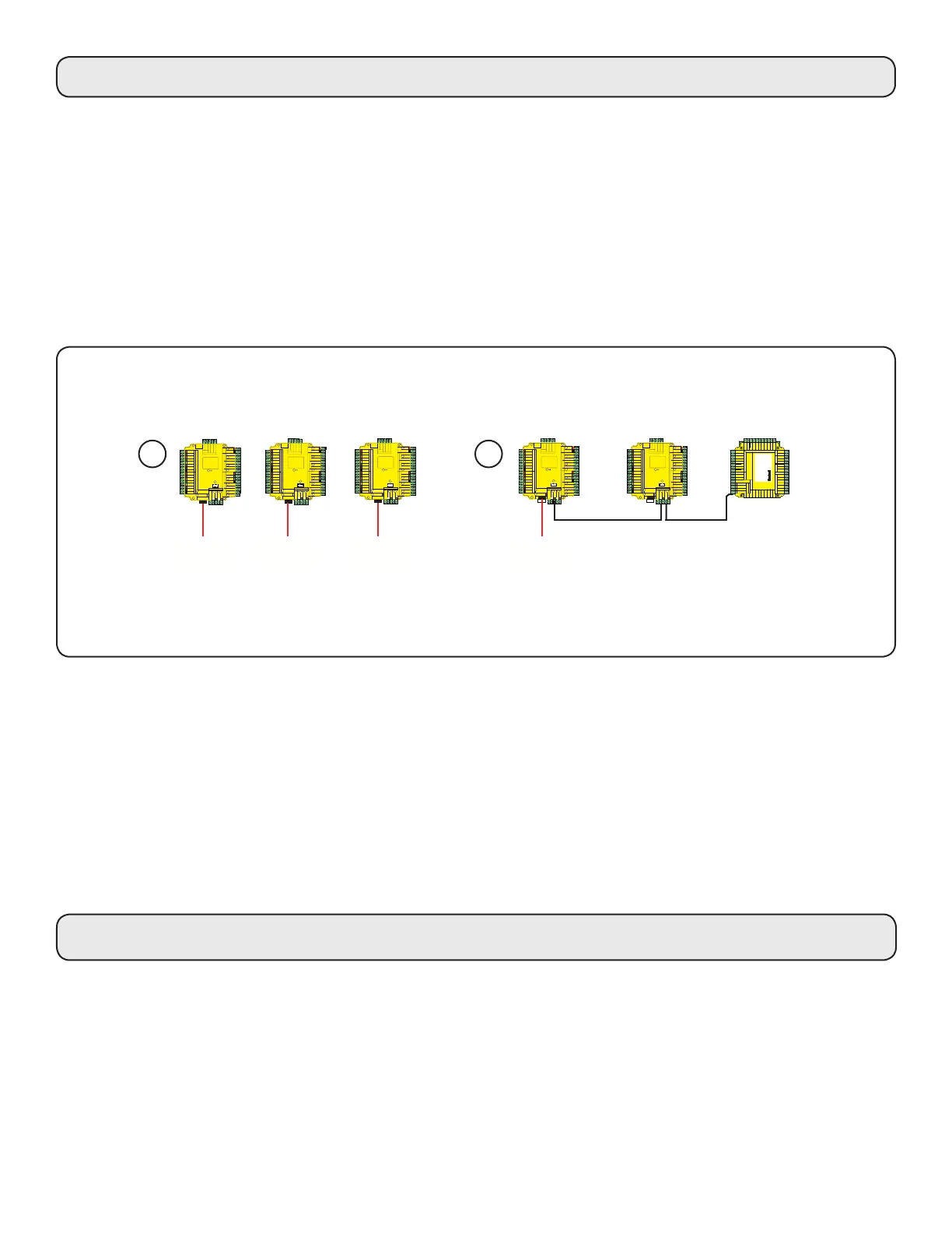
Site Layout Examples
The ACU's will continue to operate in a 'standalone' mode if the PC is shut down or the dataline is disconnected.
Any Events that occur during this period are stored in the ACU and the PC is updated when it comes back on line.
The PC must be running for any 'server based' functions to operate. (Antipassback, Time and Attendance, etc).
The ACU shall be installed within the protected premises as both the power and lock wiring is present at the PCB.
A Tamper alarm input is provided on the PCB - See Input/Output Wiring
1 redaeR
:noi
tuaC ylno sredaer CD V21 roF
2
re
d
aeR
12V
Red LED
Amber LED
Green LED
Data/D0
Clock/D1
Media Detect
0V
12V
Red LED
Amber LED
Green LED
Data/D0
Clock/D1
Media Detect
0V
N.C.
N.O.
COM
N.C.
N.O.
COM
Alarm
12V
Green LED
Exit
0V
stupnI
tputsuO
reo
0V
12V
Contact
0V
0V
amper
repma/
tcatnoC
nottu tixE
2 yaleR
1 yaleR
Expansion
Rx
x
R Netork
CA Cable Codin
nrG
/t
erap
s
ro neerc
atad mor seroc
elbac
nee
rG
nrO/t
en
arO
10/100 Eternet
erer Connected
erer Link
100
10
End o Line ermination
ON
OFF
Net2 plus
LACE ERIAL
NMER
LAEL ERE
Intruder Alarm
et
V0
mrA
esne
MOC
.O.N
Net2 plus
1 redaeR
:noi
tuaC ylno sredaer CD V21 roF
2
re
d
aeR
12V
Red LED
Amber LED
Green LED
Data/D0
Clock/D1
Media Detect
0V
12V
Red LED
Amber LED
Green LED
Data/D0
Clock/D1
Media Detect
0V
N.C.
N.O.
COM
N.C.
N.O.
COM
Alarm
12V
Green LED
Exit
0V
stupnI
tputsuO
reo
0V
12V
Contact
0V
0V
amper
repma/
tcatnoC
nottu tixE
2 yaleR
1 yaleR
Expansion
Rx
x
R Netork
CA Cable Codin
nrG
/t
eraps
ro neerc
atad mor seroc
elbac
nee
rG
nrO/t
en
arO
10/100 Eternet
erer Connected
erer Link
100
10
End o Line ermination
ON
OFF
Net2 plus
LACE ERIAL
NMER
LAEL ERE
Intruder Alarm
et
V0
mrA
esne
MOC
.O.N
Net2 plus
Net2 plus
TCP/IP
LAN
TCP/IP
LAN
TCP/IP
LAN
Here are two typical site layouts.
1 - The Net2 plus ACU's can be individually connected to the Net2 PC via the site LAN network.
2 - The Net2 plus ACU can be used as the TCP/IP converter for a line of Net2 plus and Net2 classic ACU's.
1
1 redaeR
:noi
tuaC ylno sredaer CD V21 roF
2
re
d
aeR
12V
Red LED
Amber LED
Green LED
Data/D0
Clock/D1
Media Detect
0V
12V
Red LED
Amber LED
Green LED
Data/D0
Clock/D1
Media Detect
0V
N.C.
N.O.
COM
N.C.
N.O.
COM
Alarm
12V
Green LED
Exit
0V
stupnI
tputsuO
reo
0V
12V
Contact
0V
0V
amper
repma/
tcatnoC
nottu tixE
2 yaleR
1 yaleR
Expansion
Rx
x
R Netork
CA Cable Codin
nrG
/t
erap
s
ro neerc
atad mor seroc
elbac
nee
rG
nrO/t
en
arO
10/100 Eternet
erer Connected
erer Link
100
10
End o Line ermination
ON
OFF
Net2 plus
LACE ERIAL
NMER
LAEL ERE
Intruder Alarm
et
V0
mrA
esne
MOC
.O.N
Red 12v dc
Brown
Orange
Green
Yellow
Blue
Mauve
Black/White
Brown
Yellow
Reader 1
Orange
Keypad 1
+12v
0v
N.C.
N.O.
Com
N.C.
N.O.
Com
Alarm Output
0v
Contact
0v
Exit
0v
Tamper
PSU
Rx
Tx
Relay 1
Relay 2
Exit
Contact
Tamper
PSU
OK
5v
12v
Red
Brown
Orange
Green
Yellow
Blue
Mauve
Black/White
Brown
Yellow
Orange
Reader 2
Keypad 2
Power
Relay 1Relay 2Inputs
Network
CAT5 cable coding
White/Green
Green
White/Orange
Orange
1
2
3
4
Screen or spare cores
from network cable
CAUTION: for 12v d.c. readers only. For
correct connection of old 5v readers, refer to
instructions.
Serial number
241821
Test ID: 012345678901
z-1440
3
248 98 000 00
4
RS485 dataline
Net2 plus Net2 classic
TCP/IP
LAN
1 redaeR
:noi
tuaC ylno sredaer CD V21 roF
2
re
d
aeR
12V
Red LED
Amber LED
Green LED
Data/D0
Clock/D1
Media Detect
0V
12V
Red LED
Amber LED
Green LED
Data/D0
Clock/D1
Media Detect
0V
N.C.
N.O.
COM
N.C.
N.O.
COM
Alarm
12V
Green LED
Exit
0V
stupnI
tputsuO
reo
0V
12V
Contact
0V
0V
amper
repma/
tcatnoC
nottu tixE
2 yaleR
1 yaleR
Expansion
Rx
x
R Netork
CA Cable Codin
nrG
/t
erap
s
ro neerc
atad mor seroc
elbac
nee
rG
nrO/t
en
arO
10/100 Eternet
erer Connected
erer Link
100
10
End o Line ermination
ON
OFF
Net2 plus
LACE ERIAL
NMER
LAEL ERE
Intruder Alarm
et
V0
mrA
esne
MOC
.O.N
Net2 plus
2
TCP/IP and RS485 LED indication
The Net2 plus performs two functions. It is an access control unit and also a TCP/IP RS485 converter. Information
can pass across the PCB between the TCP/IP and RS485 data port but is not relevant to this ACU
- Server Connected LED (Steady Green)
This LED shows that the TCP/IP interface is active and receiving data from the Net2 PC server. This includes all data
for other ACU's that may be linked via the RS485 data port.
- Rx and Tx LED's
These LED's show the activity for this ACU only. This is same indication as seen on a Net2 classic ACU.
It is not dependant on the source (TCP/IP or RS485). The Rx LED will ash for all data being received and the Tx
LED will only ash when this unit responds to its own address.
 Loading...