PAGE 7
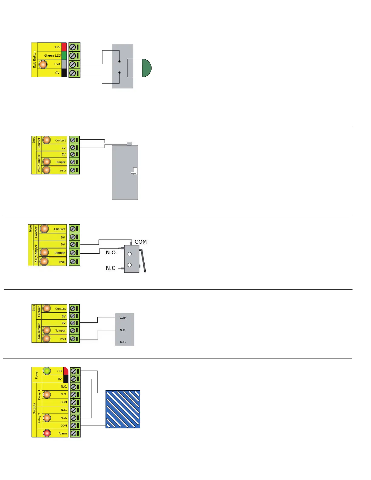
INPUT / OUTPUT WIRING
Exit button
Door Contact
Tamper switch
PSU monitoring
Door Bell - Relay 2
The ACU supplied in a plastic housing has a 'NO' tamper
switch tted and pre-wired into the circuit board.
A NO switch may be tted so that it is held closed while
the door is shut.
The Contact LED will be ON when the switch is closed.
- Door Closed.
The PSU LED will be ON when the NO Relay contacts are
closed. - Power OK.
Where tted, a 'push to make' button is required.
(See Specication table for ratings)
The Exit LED will be ON when the switch is closed. -
Button Pushed.
When the Exit terminal is shorted to 0V, the Exit LED will illuminate and the ACU will operate Relay 1.
The reader/exit button Green LED will ash during this period. More than one exit button can be wired in
parallel. Relay 1 will remain transfered while the short to 0V remains.
When connected, Net2 will check the door position during
access activity and will raise an Alarm in the event of a
'Door Forced' or 'Door left open' condition.
The Tamper LED will be ON when the switch is closed.
Net2 will monitor the switch position and will raise an
Alarm in the event of a 'Tamper' condition.
The Net2 software will monitor the relay contacts
and will raise an Alarm in the event of a 'Power Fail'
condition.
Pressing the bell button on the keypad will result in
Relay 2 being energized for 1 second. A bell sounder
can be controlled by wiring one of the bell feeds
across COM / NO on the relay.
See Specication table for Output Ratings
Connect to a UL listed burglar alarm unit for supervision.