PAGE 5
90% of installation faults are caused by wiring errors on the RS485 data line.
Special attention to this area can save time and effort.
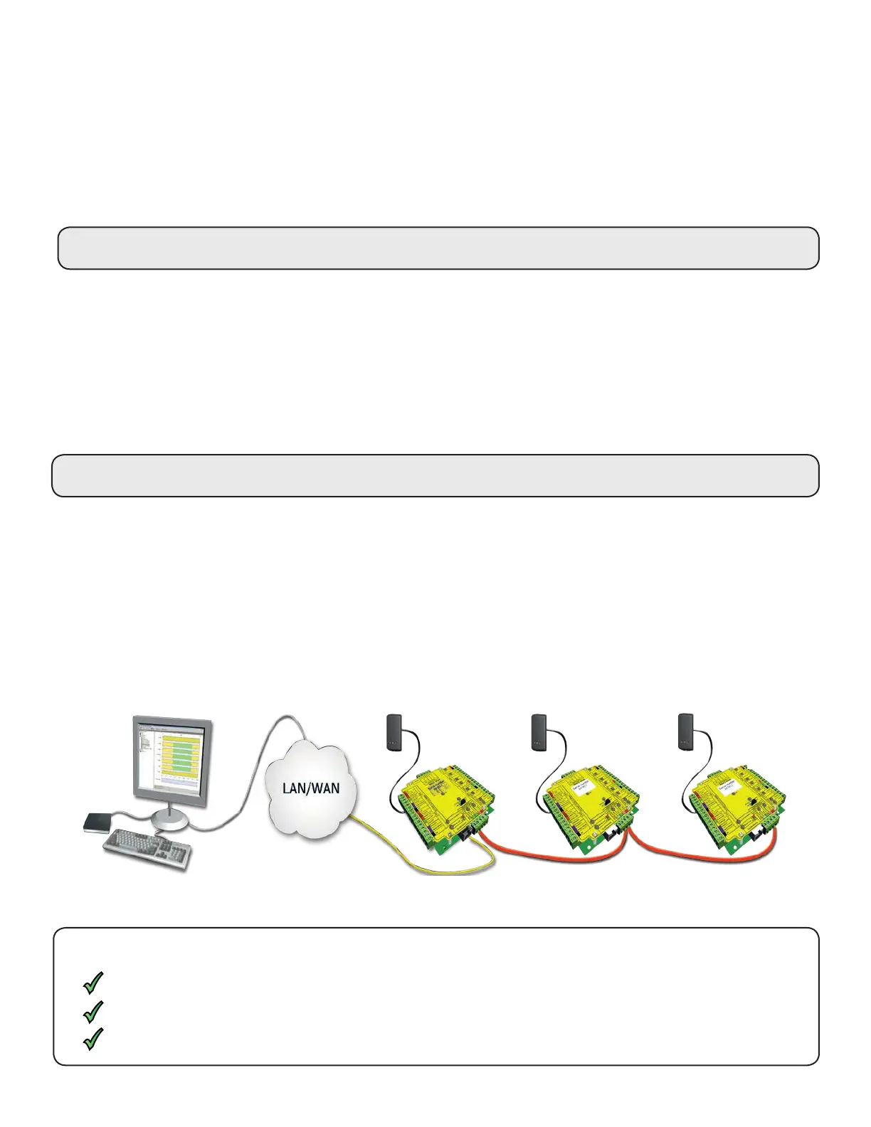
Connecting to the PC or other ACU's via the RS485 data connection
Reader & Data Cable Screens
- Data cable screens and spare cores MUST be connected throughout.
- Reader and keypad screens where provided, should be connected to the Black 0V terminal.
The data line must be wired in a single daisy chain. The data connection to the PC may be located at any position
along the data line.
TCP/IP Loopback test
The following test should be run if there are problems setting up the IP conguration of the interface. This test
sends data to the device and checks this against the data it receives back. This conrms that the network pathing
is working correctly.
The Net2 server program must be shut down during this test.
Remove any wires from the RS485 data line connector and create a hardwired data loop as follows. Connect the
Orange to White/Green and Green to White/Orange. To run the test, click the Loopback button in the advanced
section of the Server Cong Utility/TCP/IP Nodes. If the test fails, connect the unit directly to the PC with a
network patch cable and test it again. Should this still fail, please call Technical Support for further advice.
Reader
Control unit
Net2
Server
Check the screen of the data cable is continuous - this provides the 0V DC system reference.
Check that there are no data line to screen shorts.
Check the resistance across each data pair is 60-80 ohms.
RS485 data line resistance check
Power down all TCP/IP, USB and RS232 converters (individual and Net2 plus).
This may require the routers and gateways to be congured between the networks. Again, this would be done by
the Network administrator of that site. Make sure the ports listed above are open on all intermediate routers.
Once installed, create a record with the;Add button (if none was created during initial set up) and you should then
be able to detect its MAC by entering the IP address in the Conguration screen Ping box.
Naming TCP/IP Ethernet interfaces
The rename button can be used to give an interface a meaningful name in the system. This can be especially
useful when more than one interface is used, as the name will appear in the doors screen within Net2 showing
which ACUs are connected to which dataline, helping in any future fault nding process.
END OF LINE TERMINATION - 120 ohm resistors must be linked across each data pair at the beginning AND end of
the line. This can be done on many units with a switch or jumpers. If not, resistors are provided with the converter.