39
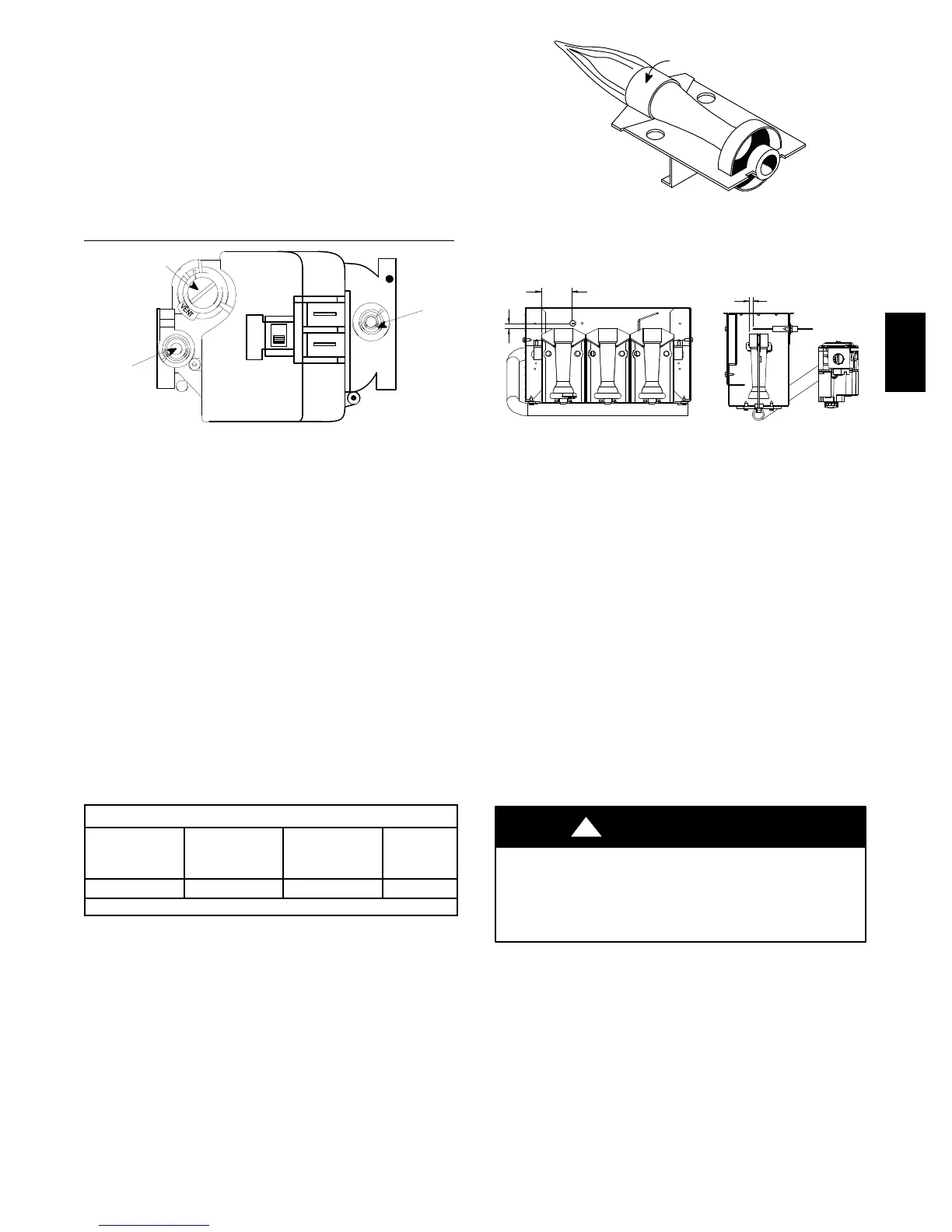
4. Turn gas ON and remove adjustment screw cover on gas
valve. Turn adjusting screw counterclockwise to decrease
manifold pressure and clock wise to increase pressure.
NOTE: Adjustment screw cover MUST be replaced on gas
control valve before reading manifold pressure and operating
furnace.
5. Set manifold pressure to value as shown in Table 6 or
Table 7 under GAS SUPPLY AND PIPING section in
this manual.
6. When the manifold pressure is properly set, replace the ad-
justment screw cover on the gas control valve.
Regulator Adjustment
Under Cap
Inlet
Pressure
Tap
1
/
8
NPT
INLET
OUTLET
Outlet
Pressure
Tap
1
/
8
NPT
IN
OFF
ON
HONEYWELL
A07732
Fig. 43 -- Typical Gas Va lve
7. Remove blower compartment door. Remove jumper wire
from thermostat connection on furnace control board. Re-
move manometer connection from manifold pressure tap,
and replace plug in manifold.
8. Check for leaks at p lug.
9. Replace the burner and blower compartment doors.
Natural Gas Input Rating Check
NOTE: The gas meter can be used to measure input to furnace.
Rating is based on a natural gas BTU content o f 1,000 BTU’s per
cubic meter. Check with gas supplier for actual BTU content.
1. Turn OFF gas supply to all appliances and start furnace.
Use jumper wire on R to W for Heat.
2. Time how many seconds it takes the smallest dial on the
gas meter to make one complete revolution. Refer to
Example.
NOTE: If meter uses a 2 cubic foot dial, divide results
(seconds) by two.
Example
Natural Gas
BTU Content
No. of
Seconds
Per H our
Time Per
Cubic Foot
in Seconds
BTU Per
Hour
1,000 3,600 48 75,000
1,000 x 3,600 ÷ 48 = 75,000 BTUH
3. Remove jumper wire from R to W.
4. Relight all appliances and ensure all pilots are operating.
Main Burner Flame Check
Allow the furnace to run approximately 10 minutes then inspect
the main burner. See Fig. 44.
Check for the following (Fig. 44):
S Stable and blue flames. Dust may cause orange tips or wisps of
yellow, but flames MUST NOT have solid, yellow tips.
S Flames extending directly from burner into heat exchanger.
S Flames do NOT touch sides of heat exchanger
.
If any problems with main burner flames are noted, it may be
necessary to ad ju st gas p ressu res, or check for drafts.
Burner Face
A07734
Fig. 44 -- Main Burner
NOTE: For Ignite location see Fig. 45
2
1/
16
(52.4)
5
/
16
(8)
1
/
4
(6.4)
A07735
Fig. 45 -- Igniter Location
Temperature Rise Check
The blower speed MUST be set to give the correct air
temperature rise through the furnace as marked on the rating
plate. Temperature rise is the difference between supply and
return air temperatu res.
To check temperature rise,use the following procedure:
1.Place thermometers in supply and return air registers as close to
furnace as possible, avoiding direct radiant heat from heat
exchangers.
2.Operate furnace continuously for 15 minutes with all registers
and duct dampers open.
3.Take reading and compare with range specified on rating plate.
4.If the correct amount of temperature rise is NOT obtained, it
may be necessary to change blower speed. A higher blower speed
will lower the temperature rise. A lower blower speed will
increase the temperature rise.
Changing Blower Speed
ELECTRICAL SHOCK HAZARD
Failure to follow this warning could result in personal injury or
death.
T ur n OFF power to furnace before changing speed taps.
!
WARNING
NOTE: The speed taps that the manufacturer sets from the
factory for this product are based on a nominal 400 CFM per ton
cooling and the basic mid range on the temperature rise for
heating.
Since the manufacturer cannot establish the static pressure
that will be applied to the unit, it is the responsibility of the
installer dealer/contractor to select the proper speed taps for
the application when the unit is installed.
If it is necessary to change speeds, refer to steps below.
PG9YAA



 To Next Page