6
Frozen Water Pipe Hazard
WATER DAMAGE TO PROPERTY HAZARD
Failure to follow this caution may result in property damage.
Do not leave your home unattended for long periods during
freezing weather without turning off water supply and
draining water p ipes or otherwise protecting against the risk
of frozen pipes and resultant damage.
CAUTION
!
Your furnace is designed solely to provide a safe and comfortable
living environment. The furnace is NOT designed to ensure that
water pipes will not freeze. It is equipped with several safety
devices that are designed to turn the furnace off and prevent it
from restarting in the event o f various potentially unsafe
conditions.
If your furnace remains off for an extended time, the pipes in
your home could freeze and burst, resulting in w ater damage.
If the structure will be unattended during cold weather you should
take these precautions.
1. Turn off the water supply to the structure and drain the wa-
ter lines if possible and add an antifreeze for potable water
to drain traps and toilet tanks. Open faucets in appropriate
areas.
-- o r --
2. Have someone check the structure frequently during cold
weather to make sure it is warm enough to prevent pipes
from freezing. Instruct them on a service agency to call to
provide service, if required.
-- o r --
3. Install a reliable remote sensing device that will notify
somebody of freezing conditions within the home.
Winter Shutdown
If you go away during the winter months and do not leave the
heat on in your home, the p lastic transition box and the
condensate trap o n the furnace must be protected from freeze
damage. (See Fig. 10 through Fig. 17)
1. Disconnect the
5
/
8
″ OD rubber hose from the vent drain
fitting that is located downstream of the combustion
blower. Insert a funnel into the hose and pour four(4)
ounces of sanitary type (RV) antifreeze into the condensate
trap. Reconnect the
5
/
8
″ OD rubber hose to the stub on the
vent drain fitting. Secure with the hose clamp.
2. Disconnect the
3
/
4
″ OD rubber hose from the condensate
trap. Insert a funnel into the hose and and pour four(4)
ounces of sanitary type (RV) antifreeze into the plastic
Transition box. Squeeze the hose together near the end and
quickly reconnect the
3
/
4
″ OD rubber hose to the stub on
the condensate trap. Secure with the hose clamp.
When you return home, your furnace will be ready to start, as it is
not necessary to drain the antifreeze from the furnace.
Installation
CARBON MONOXIDE POISONING HAZARD
Failure to follow this warning could result in personal injury or
death.
This furnace can NOT be common vented or connected
to any type B, BW or L vent or vent connector, nor to
any portion of a factory--built or masonry chimney. If
this furnace is replacing a previously common-vented
furnace, it may be necessary to resize the existing vent
and chimney to prevent oversizing problems for the
other
remaining appliance(s). See Venting and Combustion Air
Check in Gas Vent Installation section. This furnace
MUST be vented to the outside.
!
WARNING
Location and Clearances
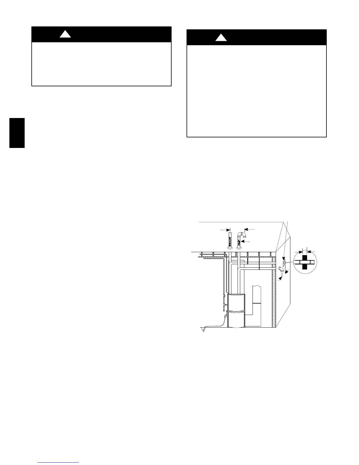
1. Refer to Fig. 1 for typical installation and basic connecting
parts required. Refer to Fig. 4 for typical horizontal direct
vent installation and basic connecting parts required. Sup-
ply and return air plenums and duct are also required.
2. If furnace is a replacement, it is usually best to install the
furnace where the old one was. Choose the location or
evaluate the existing location based upon the minimum
clearance and furnace dimensions (Fig. 2).
Vent Pipes MUST be
supported Horizontally
and Vertically
*8″ Min.
20′ Max.
in same atmospheric
zone
*8″ Min.
20′ Max.
in same
atmospheric
zone
Coupling on ends of
exhaust pipe. Total
pipe & coupling out-
side structure = 8″
Aluminum or non- rusting shield recommended. (See
Vent Termination Shielding for dimensions).
*
Increase minimum from 8″ to 18″ for cold climates (sustained temperatures 0 ° F
and below for 24 or more consecutive hours).
DISCHARGE AIR
Inlet Pipe (not
used on Single
Pipe model)
A07700
Fig. 1 -- Typical Upflow Installation
PG9YAA
 Loading...