11
Chapter 2: Motherboard Installation
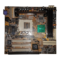
Install The Motherboard
Install the motherboard in a system chassis (case). The board is an micro-ATX size
motherboard. You can install this motherboard in an ATX case. Make sure your case
has an I/O cover plate matching the ports on this motherboard.
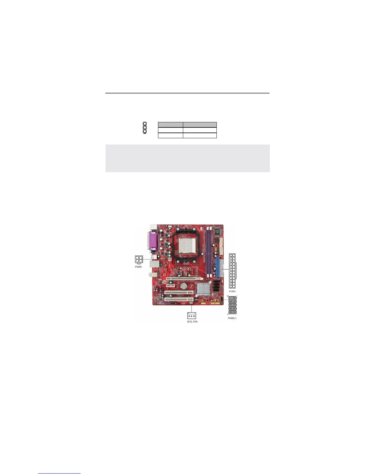
Connect the power connector from the power supply to the PWR1 connector on
the motherboard. PWR2 is a +12V connecotr for CPU Vcore power.
If there is a cooling fan installed in the system chassis, connect the system cooling
fan cable to the SYS_FAN fan power connector on the motherboard.
Connect the case switches and indicator LEDs to the PANEL1 header.
Install the motherboard in a case. Follow the case manufacturer’s instructions to
use the hardware and internal mounting points on the chassis.
USBPWR_R: REAR USB PS/2 POWER SELECT Jumper
Use this jumper to set the Rear USB PS/2 Power function.
Function Jumper Setting
VCC5 Short Pins 1-2
VCC5_DUAL Short Pins 2-3
USBPWR_R
1
Note:1. Make sure the power supply provides enough VCC5_DUAL voltage
before selecting the VCC5_DUAL function.
2. It is required that users place the USBPWR_F & USBPWR_R cap onto
2-3 pin rather than 1-2 pin as default if you want to wake up the
computer by USB/PS2 KB/Mouse.