12
Motherboard User’s Guide
Pin Signal Pin Signal
1 HD_LED_P(+) 2 FP PWR/SLP(+)
3 HD_LED_N(-) 4 FP PWR/SLP(-)
5 RESET_ SW_ N( - ) 6 POWER_ SW_P( +)
7 RESET_ SW_ P(+) 8 POWER_ SW_N( - )
9RSVD 10KEY
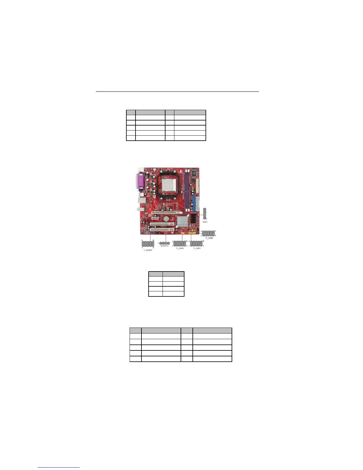
SPK1: Speaker Header
Connect the cable from the PC speaker to the SPK1 header on the motherboard.
F_AUDIO: Front Panel Audio Header (optional)
This header allows the user to install auxiliary front-oriented microphone and line-
out ports for easier access.
Pin Signal
1VCC
2Key
3GND
4 Signal
Pin Signal Pin Signal
1PORT 1L 2GND
3 PORT 1R 4 PRESENCE#
5 PORT 2R 6 Sense1_return
7 SENCE_SEND 8 KEY
9 PORT 2L 10 Sense2_return
Connecting Optional Devices
Refer to the following for information on connecting the motherboard’s optional
devices:
Here is a list of the PANEL1 pin assignments.