13
Chapter 2: Motherboard Installation
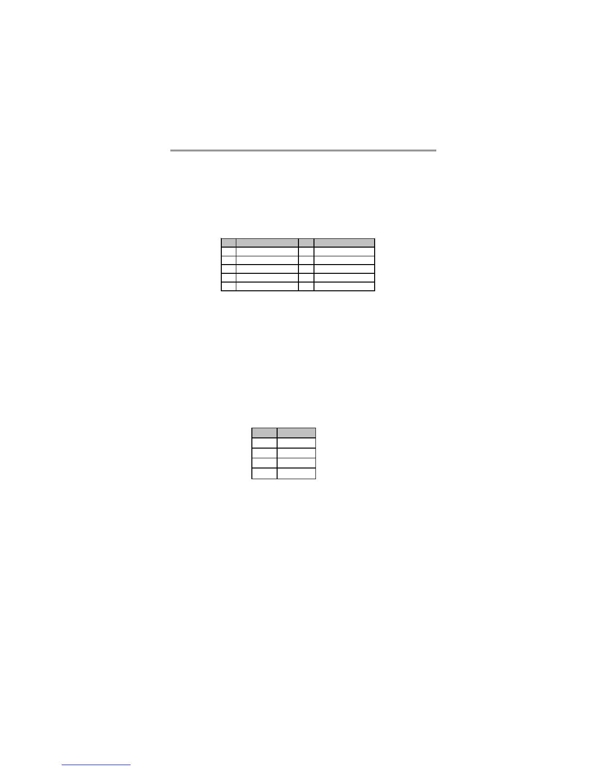
Here is a list of USB pin assignments.
1. Locate the F_USB1~3 header on the motherboard.
2. Plug the bracket cable onto the F_USB1~3 header.
3. Remove a slot cover from one of the expansion slots on the system chassis.
Install an extension bracket in the opening. Secure the extension bracket to
the chassis with a screw.
Pin Signal Pin Signal
1 USBPWR0 2 USBPWR0
3 USB _FP_ P0( - ) 4 USB_FP_P1( - )
5USB_FP_P0(+) 6USB_FP_P1(+)
7GND 8GND
9KEY 10USB_FP_OC0
F_USB1~3: Front Panel USB Headers
The motherboard has USB ports installed on the rear edge I/O port array. Addition-
ally, some computer cases have USB ports at the front of the case. If you have this
kind of case, use auxiliary USB headers F_USB1~3 to connect the front-mounted
ports to the motherboard.
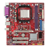
Pin Signal
1SPDIFOUT
25VA
3Key
4GND
SPDIFO1: S/PIF Out Header
S/PDIF (Sony/Plilips Digital Interface) is a standard audio transfer file format and
allows the transfer of digatal audio signals from one device to another without
having to be converted first to an analog format. Via a specific audio cable, you can
connect the SPDIFO1 header (S/PDIF output) on the motherboard to the S/PDIF
digital input on the external speakers or AC Decode devices.