71
L510010-11
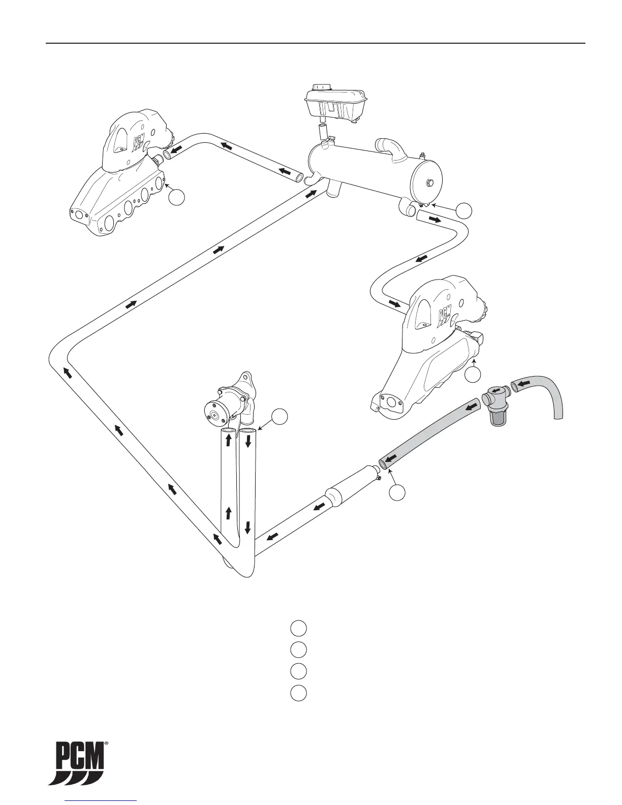
Figure 15-7 Direct Drive Fresh-Water Cooling System ZR409 / ZR450
WATER FLOW DIAGRAMS - 15
Note: This diagram is for illustration purposes
only. The actual routing and/or shape of the
hoses may vary slightly depending on installation.
1
1
2
2
3
4
4
4
3
Drain Locations
- Transmission Cooler - Remove Inlet Hose
- Raw Water Pump - Remove Outlet Hose
- Heat Exchanger - Remove Drain Plug/Zinc Anode
- Exhaust Manifolds - Remove Drain Plugs
 Loading...