Home
Peavey
Amplifier
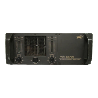
CS 1200
Peavey CS 1200 User Manual
4
of 1
of 1 rating
12 pages
Give review
Manual
Specs
To Next Page
To Next Page
To Previous Page
To Previous Page
Loading...
MAINS
POWER
SWITCH
(5)
The
tront
panel
of
the
CS-1200
contains
a
conventional
type
on/off
rocker
switch.
When
the
amplifier
is
plugged
into
a
suitable
power
source,
activating
this
switch
should
light
both
channel
"O’
array
LED's
afterthe
power-updelay
sequence
is
completed
(approximately
two
seconds).
You
should
also
be
ableto
hear
the
output
relays
close
(click).
If
the
amplifier
is
cool,
the
fan
should
start
on
low
speed
operation.
If
only
one
channel
"0”
indicator
lights,
then
the
possibility
exists
that
the
mains
fuse
on
the
other
channel
has
blown.
If
neither
channel
"0"
indicator
lights,
then
check
the
main
power
source.
It’s
always
a
good
idea
to
check
to
see
that
the
fan
is
operational,
especially
on
a
new
unit.
The
possibility
existsthat
due
to
shipping
and
handling,
thcfan
bearings
might
be
too
tight
to
allow
low
speed
fanoperation.
If
This
isthecase,
immediately
seek
professional
help.
The
CS-1200
must
have
normal
fan
operation
to
provide
adequate
cooling
for
the
unit.
Without
airflow,
the
amplifier
will
'‘thermal”
very
quickly
under
any
signal
conditions.
BACK
PANEL
(6)
The
back
panel
of
the
CS-1200
contains
a
“back
porch”
design
which
contains
the
various
input
and
output
connectors
for
each
channel.
Also
included
is
the
patch
panel
to
provide
the
user
with
a
very
flexible
system
to
facilitate
the
use
of
balanced
input
transformers
and
dual
crossover
networks.
These
features
are
unduplicated
in
any
other
stereo
power
amp
on
the
market
today
The
back
panel
also
includes
the
fan
opening
with
protective
grille
(6)
where
cooling
air
is
drawn
into
the
amplifier.
This
opening
should
never
be
blocked
or
restricted.
8
/
\
7
6
_J
_
g'
n
©
i.
■
lUXl-AO
IS
/
—
/
T&r
A
wuettf
MMH64E*
V<4
MiCI
*411
4
A
CS'-1200^/
evaiE
Diiyi
OD’~
ncNP*!iSor.
/
/
/
\
\
i
j
oic,,--
*»•
-.M
1.>I.V
AVIS.
BJWB
OO^tJ
rjwjjjtu
.-i
\
_
V
/
/
FUSES
(8)
Each
channel
of
the
CS-1200
is
fused
with
a
standard
10
amp.
125
VAC
fuse.
Always
replace
with
the
same
type
and
rating.
Failure
to
do
this
could
void
the
warranty
on
the
CS-1200.
MODE
SWITCH
(16)
The
mode
switch
is
located
on
the
“back
porch”
next
to
the
channel
input
jacks.
This
switch
converts
the
CS-1200
from
normal
stereo
mode
to
bridge
mode.
Unless
theamplifier
isto
be
used
in
a
commercial
sound
distribution
system
(70/100volt
lines),
the
bridge
modeshould
not
be
used.
In
certain
crossover
applications,
accidental
switching
to
the
bridge
mode
could
destroy
the
speaker
system.
Applications
of
the
bridge
mode
will
be
covered
later
in
this
manual.
PATCH
PANEL
The
patch
panel
of
the
CS-1200
offers
many
features
that
make
the
amplifier
more
flexible.
In
order
to
simplify
the
explanation,
four
basic
modes
of
operation
will
be
introduced.
Simplified
functional
diagrams
are
printed
on
the
top
of
the
CS-1200
showing
these
four
modes.
These
diagrams
also
appear
in
this
manual
for
discussion
purposes.
CS-1200
PATCH
PANEL
(STEREO
MODE)
WITH
JUMPERS
TRANSFORMER
i.
2
-
GRCUNO
3
-
POSITIVE
X
OVER
4
6
Other manuals for Peavey CS 1200
Owner's Manual
48 pages
4
Based on 1 rating
Ask a question
Give review
Questions and Answers:
Need help?
Do you have a question about the Peavey CS 1200 and is the answer not in the manual?
Ask a question
Peavey CS 1200 Specifications
General
Channels
2
Signal to Noise Ratio
> 100 dB
Input Impedance
20k ohms balanced, 10k ohms unbalanced
Weight
35 lbs
Dimensions
3.5" H x 19" W x 15.25" D
Related product manuals
Peavey CS 1200X
22 pages
Peavey CS 1200H
20 pages
Peavey CS 1000
12 pages
Peavey CS 1000X
20 pages
Peavey CS 800
11 pages
Peavey CS-900
14 pages
Peavey CS 6000
14 pages
Peavey CS 200X
12 pages
Peavey CS 3000G
28 pages
Peavey CS 800x4
52 pages
Peavey ICA 1200
64 pages
Peavey Combo
4 pages