EasyManuals Logo

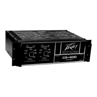
Peavey CS-400 User Manual

Peavey CS-400
8 pages
To Next Page IconTo Next Page
To Previous Page IconTo Previous Page
Page #3 background imageLoading...
Page #3 background image
CLIPPING/COMPRESSION
LED
INDICATOR
The
clipping/compression
LED
(light
emitting
diode)
indicator
(1),
with
the
compressor
operational,
indicates
when
compression
takes
place.
As
long
as
gain
reduction
is
occurring,
the
LED
will
continue
to
light
thereby
giving
a
valuable
indication
of
this
unique
compression
function.
When
the
compressor
is
defeated
by
pulling
out
the
level
control
on
the
associated
channel
(2),
the
LED
now
indicates
a
condition
called
"clipping.”
This
condition
is
simply
the
failure
of
the
amplifier
to
faithfully
reproduce
the
input
signal.
Clipping
can
be
caused
by
low
line
voltage,
shorted
speaker
cables,
or
simply
overdriving
the
amplifier
with
too
much
signal.
In
any
event,
the
LED
will
light
when
this
occurs
and
it
has
a
short
memory
circuit
built
in
to
give
the
soundman
a
positive
indication.
The
LED
indicator
will
light
during
every
clipping
situation,
thereby
providing
a
valuable
tool
to
help
prevent
severe
distortion
of
the
CS-400
.
This
type
of
indicator
is
more
valuable
than
a
conventional
VU
meter
because
a
VU
meter
tends
to
ignore
occasional
peaks
and
only
responds
to
relatively
long
term
signals.
INPUT
SENSITIVITY
CONTROLS
The
CS-400
has
the
level
controls
for
each
channel
labeled
in
a
more
functional
manner
replacing
the
conventional
0
to
10
segmented
circle
with
the
actual
input
sensitivity
ratings
of
the
amp
for
various
settings
of
this
control.
In
the
past,
this
control
has
often
confused
even
the
most
experienced
audio
technician
as
to
its
purpose
and
usage.
This
new
change
will
help
to
explain
its
fOnction,
the
need
for
these
controls
and
the
significance
of
the
sensitivity
rating.
The
input
sensitivity
rating
of
a
power
amplifier
is
the
RMS
voltage
level
required
at
the
input
to
produce
full
power
into
the
rated
load
at
the
output
This
voltage
then
becomes
the
level
at
which
the
associated
mixer
must
operate
in
order
to
produce
the
rated
full
power
output.
Operation
at
levels
above
this
rating
will
cause
the
power
amplifier
to
clip
(produce
distortion)
unless
the
associated
amplifier
has
a
compressor
or
limiter
to
minimize
this
distortion.
Such
a
system
called
“DDT®”
(U.S.
Patent
#4,318,053)
is
available
on
all
Peavey
power
amplifiers
and
the
advantages
should
be
obvious...without
it
the
sound
engineer
must
“ride
gain”
on
the
mixer
in
order
to
prevent
the
mixer
from
producing
an
output
signal
level
above
the
input
sensitivity
rating
of
the
power
amplifier
which
would
cause
distortion.
Traditionally
the
input
sensitivity
rating
of
a
power
amplifier
receives
low
“billing”
on
a
typical
specification
sheet.
Usually
the
power
output
levels
into
various
loads
and
the
distortion
numbers
are
first,
followed
by
various
other
“interesting”
specs,
such
as
damping
factor,
slew
rate,
transient
intermodulation
distortion,
and
others.
Then,
in
the
fine
print,
one
might
find
the
input
sensitivity
rating...then
again,
one
might
not.
This
rating,
however,
must
be
known
to
have
performance
visibility
at
the
mixer.
Further,
the
rated
sensitivity
is
only
correct
if
the
power
amplifier
level
control
is
set
at
the
full
clockwise
or
maximum
setting.
Any
other
setting
increases
the
value.
With
a
numbered
circle
from
0
to
10
this
new
higher
value
is
not
indicated.
The
sensitivity
ratings
of
the
CS-400
(and
CS-800
)
is
to
make
the
sensitivity
rating
known
and
to
allow
it
to
be
adjusted
accurately
to
higher
values
if
necessary.
You
will
notice
that
the
sensitivity
ratings
are
specified
in
both
RMS
voltage
levels
(usually
given
in
power
amp
spec
sheets)
and
the
equivalent
dBV
values
(usually
listed
in
typical
mixer
specs).
The
dBV
values
are
more
useful
since
most
contemporary
mixers
employ
LED
arrays,
calibrated
in
sensitivity
rating
in
dBV,
indicating
mixer
output
levels.
Knowing
the
power
amplifier
sensitivity
rating
in
dBV
will
allow
the
mixer
operator
to
know
the
status
of
his
power
amplifiers
(whether
they
are
clipping
or
not)
by
noting
which
LED
on
the
mixer
is
“peaking”.
Obviously
the
LED
labeled
the
same
or
closest
to
the
sensitivity
rating
will
indicate
full
power
output
of
the
system
Operation
below
that
point
will
indicate
how
much
so
called
“power
amplifier
headroom’’
is
left.
Operation
above
that
point
will
cause
clipping
(or
compression
if
the
Peavey
DDT
system
is
in
use).
Perhaps
an
example
will
be
helpful
here.
Referring
to
the
CS-400
faceplate
you
will
notice
that
with
the
amplifier
“sensitivity
for
rated
power”
control
set
full
clockwise,
the
rating
is
1,0V
RMS
or
0
dBV.
The
critical
LED
on
the
driving
mixer
then
is
the
one
labeled
0
dBV.
It
will
correlate
with
the
power
amplifier
clipping
/compression
LED
in
that,
whenever
the
0
dBV
LED
on
the
mixer
flashes
on
peaks,
the
LED
on
the
power
amplifier
will
also
flash
indicating
full
power
output
is
achieved
If
the
CS-400
control
were
adjusted
to
a
higher
value,
then
this
new
value
would
become
the
new
correlation
point
on
the
associated
mixer.
This,
then,
is
the
main
reason
for
knowing
the
value
of
the
power
amplifier
sensitivity.
There
is
a
very
simple
“rule”
regarding
the
setting
of
the
sensitivity
(or
level)
control
on
a
power
amplifier.
The
“rule”
is:
"UNLESS
THERE
IS
A
SPECIFIC
REASON
NOT
TO,
THE
SENSITIVITY
CONTROL
ON
ANY
POWER
AMPLIFIER
SHOULD
BE
SET
TO
THE
FULL
CLOCKWISE
POSITION,
RESULTING
IN
THE
MINIMUM
VALUE
OF
SENSITIVITY
RATING.”
The
exceptions
to
the
full
clockwise
“rule”
involve
large
systems
where
it
is
often
necessary
to
employ
several
power
amplifiers
supplying
the
same
signal
to
multiple
speaker
systems
to
achieve
the
necessary
sound
pressure
levels
or
audience
coverage.
If
the
various
amplifiers
have
different
sensitivity
ratings,
it
is
necessary
to
adjust
them
to
all
have
the
same
value
so
they
all
reach
full
power
at
the
same
time
A
typical
example
is
using
a
CS-400
and
a
CS-800
on
the
same
mixer
signal
output.
The
CS-400
is
rated
at
0
dBV,
while
the
CS-800
is
rated
at
+3
dBV
(the
CS-
800
has
3
dB
more
power
thus
requiring
3
dB
more
signal
input).
To
achieve
simultaneous
full
power
operation,
the
CS-400
should
be
adjusted
to
+3
dBV.
Notice
the
CS-800
must
be
set
full
clockwise.
The
resulting
system
will
have
15
dB
of
compression
capability.
Several
competitive
power
amplifiers
on
the
market
have
sensitivity
ratings
of
+6
dBV
(2V
RMS).
If
these
are
employed
in
multiple
systems,
obviously
the
more
sensitive
power
amps
must
be
adjusted
accordingly.
In
order
to
achieve
the
necessary
sound
pressure
levels
required
in
the
typical
“rock’n
roll”
concerts
for
the
sound
system,
the
use
of
bi-amped
and
tri-amped
systems
has
become
very
popular
and
necessary.
In
this
case,
a
crossover
system
must
be
employed
between
the
mixer
output
and
the
various
power
amplifier
systems
in
order
to
achieve
2
or
3-way
operation
with
the
associated
loudspeaker
components.
Often
these
crossover
systems
provide
adjustments
for
the
crossover
frequencies
but
have
no
level
adjustments
on
the
various
outputs
to
compensate
for
differences
in
efficiency
ratings
of
the
various
loudspeaker
components.
In
this
case,
the
sensitivity
control
can
be
adjusted
upward
on
the
particular
amp
the
amount
necessary
to
“pad”
the
associated
speaker
component
in
order
to
achieve
a
“flat”
system.
Naturally
for
optimum
compression
performance,
the
“unpadded”
power
amplifier
should
be
set
full
clockwise.
Here
at
Peavey,
we
have
chosen
a
unique
plug-in
crossover
system,
used
in
conjunction
with
our
so-called
“crossover
islands”
on
the
CS-
400
and
CS-800
,
to
achieve
bi-amped
and
tri-amped
systems
easily
and
at
a
low
cost
to
the
user.
For
each
of
our
“bi-ampable”
speaker
systems
we
offer
a
matching
crossover
“can”
which
is
specifically
designed
for
that
speaker
system
and
contains
all
the
necessary
“padding
and
equalization
to
achieve
a
“maximally
flat
system.
In
this
case,
again,
the
sensitivity
controls
on
the
associated
power
amplifiers
must
be
set
at
the
full
clockwise
setting
to
achieve
optimum
performance.
We
also
offer
general
purpose
crossovers
for
competitive
speaker
enclosures
which
do
not
contain
padding
or
equalization
(referred
to
as
“flat”
crossovers)
and,
in
this
case,
the
power
amplifier
sensitivity
controls
or
some
other
means
must
be
employed
to
accomplish
the
necessary
padding
requirements.
One
final
point
on
setting
power
amplifier
sensitivity
controls...often,
especially
in
small
clubs,
churches,
and
studio
applications,
the
full
power
output
capability
of
the
power
amplifier
is
not
needed,
or
at
the
very
most,
there
is
no
requirement
for
large
amounts
of
compression
capability
due
to
the
relatively
low
signal
levels
involved.
Simultaneously
these
applications
usually
require
a
very
low
noise
system.
In
this
case
it
is
possible
to
reduce
the
overall
system
noise
at
the
expense
of
compression
capability
by
increasing
the
power
amplifier
sensitivity
accordingly
In
other
words
if
instead
of
a
sensitivity
rating
of
0
dBV
on
the
Peavey
CS-400
,
we
adjusted
it
to
a
rating
of
+10
dBV,
overall
system
noise
would
be
improved
by
10
dB
with
the
resulting
compression
capability
of
8
dB.
In
other
words,
this
can
be
one
good
reason
for
increasing
the
power
amplifier
sensitivity
rating.
Remember,
however,
once
this
is
done,
the
mixer
operator
cannot
re-establish
full
compression
performance
sitting
at
the
mixer
If
he
wants
it
back
he
has
to
do
it
at
the
power
amplifier.
“ON/OFF”
SWITCH/PILOT
LAMP
The
front
panel
of
the
CS-400
contains
a
conventional
type
“ON
/OFF"
switch
(3)
with
an
internal
pilot
lamp.
When
the
amplifier
is
pluqqed
into
a
suitable
power
source,
activating
this
switch
should
light
the
pilot
indicator
lamp.
Failure
of
the
pilot
lamp
to
come
on
may
indicate
the
line
fuse
has
blown
or
the
power
source
is
faulty.
FAN
SPEED
SWITCH/HIGH
TEMP.
INDICATOR
The
fan
speed
switch
(4)
determines
the
speed
of
the
internal
cooling
fan
with
the
internal
lamp
indicating
over
:
t
emperature
shutdown
conditions.
For
most
applications,
low
speed
operation
will
provide
adequate
cooling.
However,
for
sustained
high
powered
applications,
manual
selection
of
high
speed
operation
is
recommended
to
provide
maximum
cooling,
thereby
minimizing
the
possibility
of
any
shutdown
of
power
due
to
over
temperature
conditions.
The
CS-400
contains
an
internal
thermal
sensor
that
automatically
raises
the
fan
speed
to
high
if
low
speed
was
selected
when
conditions
exist
which
require
additional
cooling.
Even
at
high
speed
operation,
however,
overloads
into
very
low
impedances
and
inadvertent
short
circuits
could
result
in
very
high
temperature
conditions
and
the
amplifier’s
thermal
overload
circuit
may
activate.
This
will
be
obvious
with
the
pilot
lamp
off
and
the
high
temperature
indicator
on.
The
cooling
fan
will
remain
on
as
long
as
the
unit
is
plugged
in.
After
the
unit
has
cooled
down
sufficiently,
the
amplifier
will
automatically
cycle
back
on
again.
If
high
ambient
temperature
conditions
exist,
such
as
in
a
closed
area

Questions and Answers:

Question and Answer IconNeed help?

Do you have a question about the Peavey CS-400 and is the answer not in the manual?

Peavey CS-400 Specifications

General IconGeneral
Minimum Load Impedance (Stereo)4 ohms
Input Impedance20 kOhms
Frequency Response20 Hz to 20 kHz
Total Harmonic DistortionLess than 0.1%
Input Sensitivity1.0V RMS for rated output
Signal to Noise Ratio>100dB
Power Output200 Watts RMS per channel at 4 Ohms

Related product manuals