EasyManuals Logo

Peavey CS-400 User Manual

Peavey CS-400
8 pages
To Next Page IconTo Next Page
To Previous Page IconTo Previous Page
Page #2 background imageLoading...
Page #2 background image
INSTALLATION
AND
CONNECTION
The
Peavey
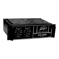
CS-400
Commercial
Series
power
amplifier
is
designed
for
durability
in
commercial
installations
and
delivers
the
quality
of
performance
required
in
studio
and
home
applications.
The
CS-400
is
a
dual
channel
power
amplifier
with
each
channel
capable
of
delivering
more
than
200
watts
RMS
into
a
4-ohm
load.
The
amplifier
is
of
the
standard
19"
rack
mount
configuration
and
is
cooled
by
an
automatic
two-speed
internal
fan.
Industrial
and
Commercial
Installation
For
commercial
and
other
installations
where
sustained
high
power
operation
is
required,
the
amplifiers
should
be
mounted
in
a
standard
19"
rack
with
one
standard
rack
space
(1
:
'A")
between
each
amplifier
in
the
stack.
It
should
be
noted
that
the
fan
pulls
air
in
from
one
side
and
exhausts
the
hot
air
through
the
opposite
side
and
top
cover.
It
is
for
this
reason
that
one
rack
space
must
be
left
between
the
units.
Adequate
air
supply
must
be
provided
for
the
amplifiers
when
rack
mounted.
The
internal
fan
must
have
a
source
of
air
that
is
not
preheated
by
other
equipment.
The
fan
may
be
operated
at
high
speed
continuously
to
provide
better
cooling
situations
at
all
times.
If
fan
cooling
is
inadequate
due
to
preheated
air
or
reduction
of
air
flow,
an
internal
thermal
breaker
may
cause
temporary
shutdown
of
the
amplifier.
This
is
indicated
by
the
front
panel
high
temperature
lamp
(4).
As
a
general
rule,
the
cooler
electronic
equipment
is
operated,
the
longer
its
useful
service
life.
You
have
invested
in
the
finest
equipment
that
money
can
buy
and
a
little
care
will
insure
long
and
reliable
operation.
Studio
and
Home
Installation
In
most
low
to
medium
power
applications,
the
power
amplifier
can
be
mounted
in
almost
any
configuration.
It
is
desirable
that,
if
at
all
possible,
the
power
amplifier
be
located
at
the
top
of
an
equipment
stack.
This
will
prevent
possible
drift
or
overheating
of
sensitive
equipment
from
the
hot
air
rising
from
the
power
amp.
As
a
general
rule,
most
home
requirements
will
never
cause
the
fan
to
switch
to
the
high
speed
mode.
Inadvertent
short
circuit
or
sustained
high
power
usage,
however,
will
cause
high
speed
fan
operation
and
could
cause
thermal
shutdown.
Input
Connections
All
input
connections
are
made
at
the
rear
panel
jacks.
The
two
jacks
marked
“Channel
Inputs”
(11)
are
wired
in
parallel
for
ease
of
connecting
several
amplifiers.
Shielded
cable
must
be
used
to
minimize
hum
and
noise
pickup.
The
nominal
input
impedance
is
50K
Ohms.
Th'is
impedance
represents
a
bridging
load
to
professional
equipment
and
is
compatible
with
the
load
requirements
of
home
stereo
devices.
The
CS-400
has
an
input
sensitivity
of
1
volt
RMS
for
rated
output
with
the
front
panel
level
set
at
“10”
allowing
complete
compatibility
in
home
applications.
This
sensitivity
decreases
at
lower
level
settings.
It
is
generally
wise
to
operate
the
level
control
at
“7”
or
greater.
Output
Connections
Two
types
of
output
connections
are
provided
on
the
rear
of
the
power
amplifier
modules.
Two
standard
]
A"
phone
jacks
(12)
and
one
set
of
binding
posts
(13)
are
available
from
each
channel.
Due
to
the
high
currents
(greater
than
10
amps)
at
full
output,
it
is
recommended
that
No.
16
or
larger
wire
be
used
whenever
possible.
Smaller
wire
sizes
will
waste
power
and
yield
less
than
optimum
results
at
the
speaker.
It
is
also
suggested
that
in
commercial
and
other
non-portable
applications,
the
binding
posts
(13)
be
used
instead
of
the
1
p
hone
plugs.
The
binding
posts
are
an
industry
standard
and
mating
banana
plugs
are
available
from
most
electronic
distributors.
As
with
all
electronic
equipment,
proper
phasing
of
the
outputs
is
important.
A
little
time
spent
in
correctly
identifying
the
wiring
could
save
a
lot
of
problems
in
the
field.
OPERATION
The
CS-400
Commercial
Series
power
amplifier
is
designed
for
maximum
ease
and
flexibility
of
operation.
When
the
unit
is
installed
and
connected
as
described
in
the
previous
sections,
operation
is
simply
turning
on
the
main
switch
and
turning
up
the
front
panel
level
controls
for
the
desired
output
level
or
until
the
front
panel
overload
LED
shows
that
the
amplifier
is
clipping
or
compressing.
ft
O
FRONT
PANEL
o
©
MTWATI
0
CHANNEL
A
ACTwimt
O
CLW9NM
CHANNEL
B
MMPRIMON
WU
TO
MHaI
©
CD
CD
It
CS-4QO
©
DDT®
COMPRESSION
The
CS-400
is
a
compact
and
powerful
amplifier
that
features
a
new
type
of
dynamic
compression.
This
compression
system
enables
the
user
to
maximize
the
performance
of
the
amplifier/speaker
combination.
We
have
determined
through
much
research
that
the
compression
circuitry
should
prevent
the
power
amp
from
running
out
of
headroom
(clipping)
and
should
be
as
simple
to
operate
as
possible
to
avoid
undue
complication
for
the
user.
The
compression
system
is
activated
by
our
exclusive
“Distortion
Detection
Technique”
circuit
(DDT®)
that
senses
conditions
which
might
overload
and
activates
compression
when
clipping
is
imminent.
In
other
words,
compression
takes
place
whenever
signal
conditions
exist
which
prevent
the
amplifier
from
faithfully
reproducing
the
input
signal.
The
threshold
is
the
clipping
level
itself
and
no
specific
threshold
control
is
provided.
This
technique
effectively
utilizes
every
precious
watt
available
from
the
power
amp.
Because
of
the
dynamics
of
music
and
vocals,
it
is
quite
common
to
activate
the
compression
circuitry
virtually
constantly
during
a
performance
since
this
is
what
it
is
designed
to
do,
i.e.,
to
maximize
the
dynamics
available
from
the
amplifier
within
its
power
output
capabilities
regardless
of
power
supply/line
voltage
variations
and
load
impedance
selection.

Questions and Answers:

Question and Answer IconNeed help?

Do you have a question about the Peavey CS-400 and is the answer not in the manual?

Peavey CS-400 Specifications

General IconGeneral
Minimum Load Impedance (Stereo)4 ohms
Input Impedance20 kOhms
Frequency Response20 Hz to 20 kHz
Total Harmonic DistortionLess than 0.1%
Input Sensitivity1.0V RMS for rated output
Signal to Noise Ratio>100dB
Power Output200 Watts RMS per channel at 4 Ohms

Related product manuals