Do you have a question about the Peavey CS 4080 HZ and is the answer not in the manual?
Detailed numbered safety instructions covering usage, cleaning, installation, and noise exposure.
Inspect amplifier for damage upon arrival and notify supplier.
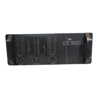
Amplifiers mount in 19" racks; rear ears for support are recommended.
Forced-air cooling system requires unobstructed airflow for optimal operation.
Ensure correct mains voltage and turn off amplifier before making audio connections.
Use three-pin XLR or 6.3 mm 'combi' connectors for input connections.
Outputs connect via binding posts or Speakon connectors using various plug types.
Verify mains voltage and turn off amplifier before connecting power.
Tables detailing power loss based on wire gauge and cable length for different impedances.
Independent channel operation with individual level control via attenuators.
Single input drives both channels; attenuators set individual levels.
Combines channels for mono output; use caution due to high voltage.
Front panel combination AC switch and circuit breaker.
Controls signal level for each amplifier channel to manage headroom.
Selects parallel or independent input connector mode.
Determines amplifier operation mode: Stereo or Bridged Mono.
Indicates channel is operational and powered on.
Illuminates when an output signal greater than 1V RMS is present.
Illuminates at onset of clipping, indicating gain reduction or clip limiting.
Reduces channel gain to prevent speaker damage from clipping.
Adjusts gain for overstressed loads and disconnects load if necessary.
Opens speaker relay if heat sink reaches 85°C to prevent overheating.
LFC circuit attenuates signal; thermal protection may disconnect load.
Opens speaker relay if DC voltage or subsonic frequencies are detected.
Mutes signals and keeps relays open for ~4 seconds during power cycling.
Instructions for obtaining service and warranty information for the amplifier.
Tables detailing rated power output at various impedances and frequency response.
Specs including Slew Rate, Damping Factor, Phase Response, Input Sensitivity, and Impedance.
| Type | Power Amplifier |
|---|---|
| Channels | 2 |
| THD (Total Harmonic Distortion) | < 0.1% |
| Signal-to-Noise Ratio | > 100dB |
| Input Sensitivity | 1.4V |
| Damping Factor | > 500 |
| Frequency Response | 20Hz - 20kHz |
| Input Impedance | 20k Ohms (balanced), 10k Ohms (unbalanced) |
| Dimensions | 19" x 3.5" x 16.5" |
| Rack Mount | 2U |