8
| VSP
ELECTRICAL CONNECTION
Make sure that there is no voltage at the terminals of the line conductors before making the connec-
tions. Also ensure the electrical power supply mains is equipped with safety devices and in particular a
high sensitivity dierential switch (30 mA, in class F or B) and a ground compliant with standards.
• Check the electricity mains power supply voltage corresponds to the voltage indicated in the VSP inverter plate
and the motor, therefore connect the ground before every other connection.
• The voltage of the VSP power line can vary in a range between +/-10% of the plate power voltage.
• Check the rated current absorbed by the VSP unit is compatible with the plate data.
• The power line must be protected by a dierential circuit breaker switch, with the characteristics listed above.
• Secure the electrical cables in the corresponding terminals using a tool of suitable size to avoid damaging the clamping
screws. Take extra care when using an electric screwdriver.
• Do not use multicore cables containing both conductors connected to inductive power loads and signal conductors such
as sensors and digital inputs.
• Make connection cables as short as possible, and avoid forming them into a spiral shape as inductive eects could damage
the electronics.
• All wiring conductors must be suitably dimensioned to withstand the loads they supply.
• The electrical wiring between the electric pump and the inverter is carried out in the factory and therefore for operation
no operation is necessary.
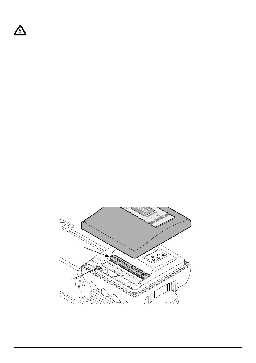
CONNECTIONS DIAGRAM
To access the terminals of the connections board, remove the cover of the inverter.
Inside the inverter there is a POWER terminal board (1) and the INPUTS/OUTPUTS terminal board (2)
See the description below of each terminal.
485_1_A
485_1_B
GND
GND
+5V
+24V
+24V
AN1
AN2
GND
GND
COM_1
NO_1
NC_1
COM_2
NO_2
NC_2
GND
IN3
GND
IN1
IN2
485_2_A
485_2_B
4-20
mA
4-20
mA
STOP
2
1