23
VSP |
ALARM DESCRIPTION
ERROR
PFC.VDC.LOW
If the VSP is found in any work mode and the voltage of the “Bus DC Link” is too low, the VSP
goes in alarm mode. In this condition the pump is blocked, at the same time the ALARM
OUTPUT relay activates, which can generate an external acoustic and visual signal.
ERROR
PFC.IN.HIGH
If the VSP is found in any work mode and the voltage of the input mains supply is too high,
the VSP goes in alarm mode. In this condition the pump is blocked, at the same time the
ALARM OUTPUT relay activates, which can generate an external acoustic and visual signal.
ERROR
PFC.IN.LOW
If the VSP is found in any work mode and the voltage of the input mains supply is too low,
the VSP goes in alarm mode. In this condition the pump is blocked, at the same time the
ALARM OUTPUT relay activates, which can generate an external acoustic and visual signal.
ERROR
PFC.HI.TEMP
If the VSP is found in any work mode and the temperature of the PFC power module is too
high, the VSP goes in alarm mode. In this condition the pump is blocked, at the same time
the ALARM OUTPUT relay activates, which can generate an external acoustic and visual
signal.
TROUBLESHOOTING
To supplement the troubleshooting guide in the alarm list, below there is also a guide to identify other possible problems.
It is assumed that the VSP was correctly connected to the power line and that the electric pumps were correctly connected
to the VSP, as described in the manual, and all the cables and connections are working.
PROBLEM AND/OR ALARM TEST TO CARRY OUT AND/OR SOLUTION
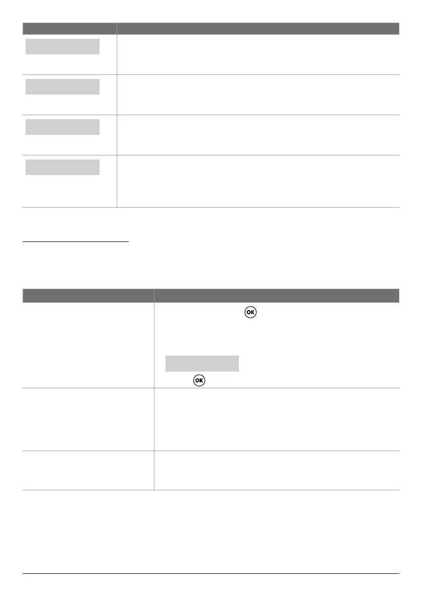
If an alarm occurs and it is not a latching
alarm, a reset must be carried out using
the following procedure
• Press the button .
• At this point on the alphanumerical part of the display, the writing appears
asking if you want to reset the alarm to zero.
Written on the display:
• Press the
key to denitively reset the alarm.
The VSP is in automatic mode but the
pump is not enabled.
• Check the correct conguration of the inputs IN1, IN2 and the PRESSURE
TRANSDUCER carried out in the conguration menu in the ADVANCED
PARAMETERS MENU.
• Check the inputs are working correctly (e.g. pressure switch connected to
IN1, IN2 or PRESSURE TRANSDUCER).
The VSP on start-up of the pump goes
to alarm mode for “MAX CURRENT”
protection.
• Check the CONF.MOTOR menu setting of the maximum current.
• Check that the motor used is working correctly.
• Latching alarm.
Continued
CLEAR ERROR?
(TYPE OF ALARM *)
(*) This eld displays the type of alarm of the VSP unit