7
VSP |
NO!
YES
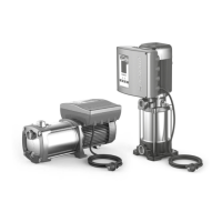
VSP-PLURIJET VSP-MK
1
2
4
3
3
4
COMPONENTS LEGEND
1. Pressure Sensor
2. Expansion tank
3. Shut-o valve
4. Check valve
5. Filter grate
6. Bottom lter with grate
POSITIONING OF THE PRODUCT
• Fasten the unit to a horizontal surface with screws.
• If the pump must be installed outside where frost can occur, protect it to avoid freezing.
For correct operation of the VSP, installation is indispensable of an adequate expansion tank
.
• The expansion tank:
– Accumulates pressurised water to reduce pump start-up to a minimum.
– It is indispensable in the presence of small system leaks.
– It absorbs any excess pressure from the system.
– The minimum volume necessary, in litres (for membrane models) is approximately equal to 10% of the maximum ow
rate of the individual pump, expressed in l/min.
Example of standard application: Qmax = 80 l/min à V = 80 x 10% = 8 litres (rounded in excess to commercial size).
– Pre-load pressure (with system empty): 70% approx. of working pressure:
Example: Pset = 4 bar à Preload pressure = 4 x 70% = 2.8 bar.
• Correctly connect the pressure sensor supplied to the system (see next chapter).
PRESSURE SENSOR
A pressure sensor is a transducer that measures the pressure of a liquid or a gas, using an electric signal sent to a receiver in
analogue format. The pressure sensors are then also called pressure transducers.
The working principle is based on the physical deformation of the strain gauge in the transducer membrane: the electrical
resistance is proportional to the pressure applied, which is converted to an electric signal, the output is transmitted in cur-
rent that varies from 4 to 20 milliampere.
The pressure sensor should be positioned on the system as indicated in the gures on the previous page.