6
| VSP
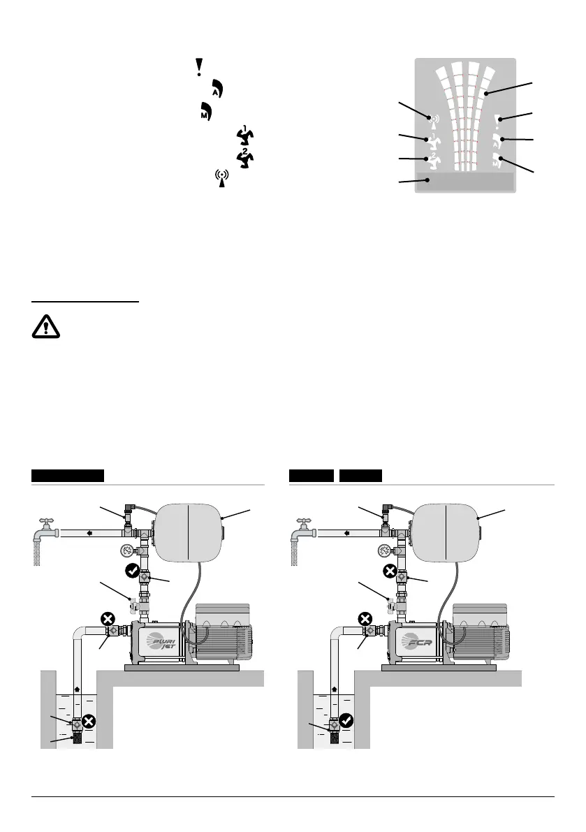
DISPLAY SYMBOLS
10. ALARM signalling indicator light
11. AUTOMATIC operating indicator light
12. MANUAL operating indicator light
13. Electric pump no. 1 running indicator light
14. Electric pump no. 2 running indicator light (if present)
15. Active WI-FI signalling indicator light
(if present)
16. Two-line alphanumeric display showing voltage, frequency, current, cosφ,
pressure, level, system operating state and system faults.
17. VSP operating status led indicator light
INSTALLATION
Incorrect installation can cause malfunctioning and breakage of the VSP.
The VSP must be installed in compliance with the following conditions.
• In a ventilated room, protected from the weather and not exposed to sunlight.
• On a solid horizontal base with screws.
• Do not install the VSP in explosive environments or in the presence of dust, acid, gas that are corrosive and/or ammable.
TYPICAL INSTALLATIONS
NO!
NO!
YES
NO!
NO!
YES
VSP-MKVSP-PLURIJET
1 1
4
2 2
4
3 3
4
6
5
4 4
VSP-FCR
STOP
15
16
12
13
11
14
10
17