10
| VSP
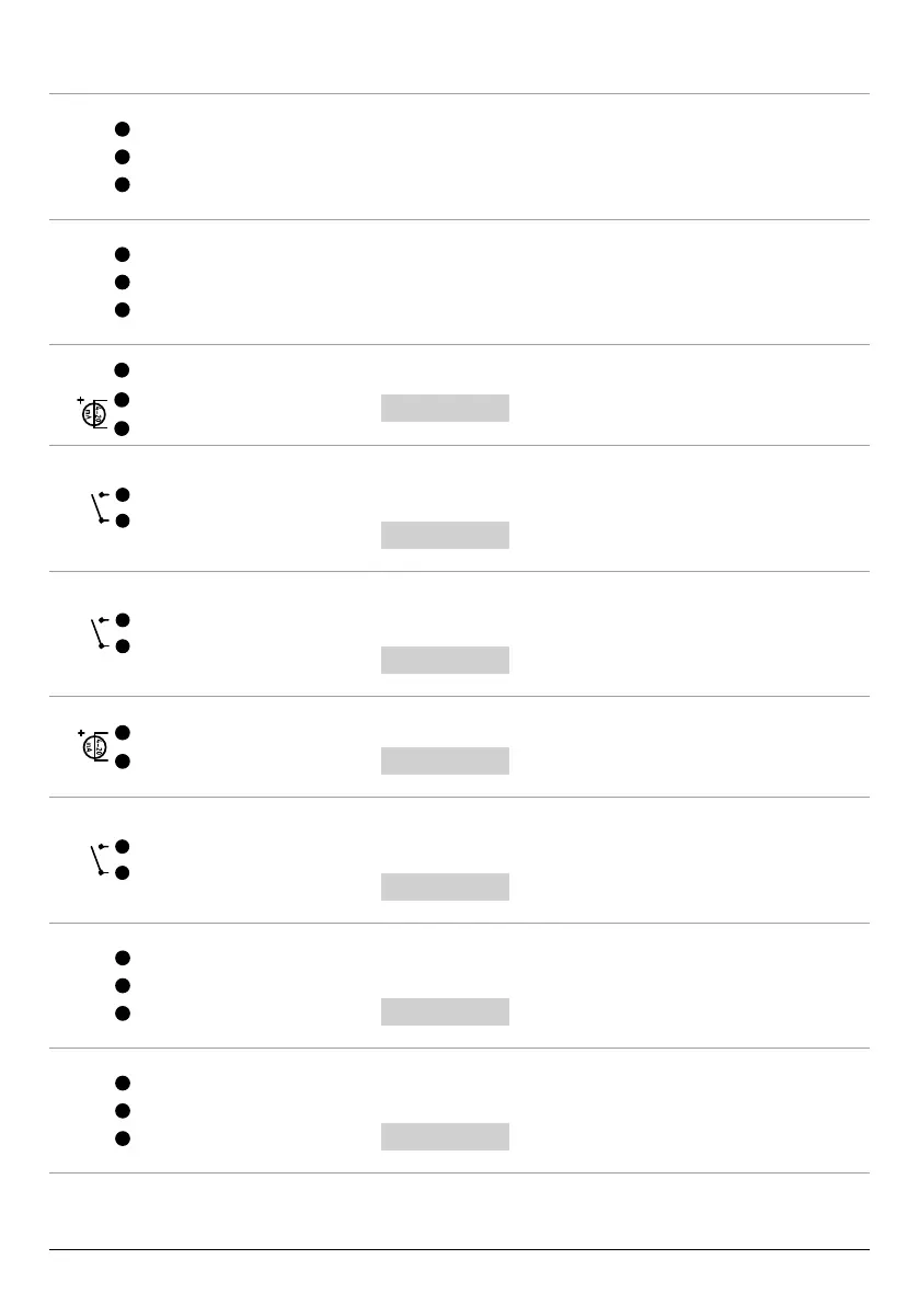
A more detailed description follows of the INPUTS/OUTPUTS TERMINAL BOARD.
485_1_A
485_1_B
GND
COMMUNICATION 1
Inputs and outputs dedicated to serial communication between multiple inverters (for a maxi-
mum of two) so they work parallel.
For further details, see the dedicated section in the part "STRUCTURE OF THE ADVANCED PARAM-
ETERS MENU".
485_1_A
485_1_B
GND
COMMUNICATION 2
Inputs and outputs dedicated to serial communication between multiple inverters (for a maxi-
mum of two) so they work parallel.
For further details, see the dedicated section in the part "STRUCTURE OF THE ADVANCED PARAM-
ETERS MENU".
4-20
mA
+5 V
+24 V
AN1
Specic rst analogue input for pressure transducer.
For further details, see
SELECT
CONF.SENS.PRE
in the part "STRUCTURE OF THE ADVANCED PARAM-
ETERS MENU".
GND
IN1
IN1
IN1
Specic rst digital input to enable the VSP for operation via
"FLUX=external minimum ow sensor" or "EXT START=start for external command".
For further details, see
SELECT
INOUT CONFIG.
in the part "STRUCTURE OF THE ADVANCED PARAM-
ETERS MENU".
IN2
IN2
GND
IN2
Specic second digital input to enable the VSP for operation via the
"SET POINT2=system second SET pressure".
For further details, see
SELECT
INOUT CONFIG.
in the part "STRUCTURE OF THE ADVANCED PARAM-
ETERS MENU".
4-20
mA
+24 V
AN2
AN2
Specic second analogue input for pressure transducer.
For further details, see
SELECT
CONF.SENS.PRE
in the part "STRUCTURE OF THE ADVANCED PARAM-
ETERS MENU".
IN3
IN3
GND
IN3
Specic third digital input to enable the VSP for operation via
"EXT ALARM =external alarm" or "EXT START=start for external command".
For further details, see
SELECT
INOUT CONFIG.
in the part "STRUCTURE OF THE ADVANCED PARAM-
ETERS MENU".
COM_1
NO_1
NC_1
OUTPUT 1 RELAY
Specic relay rst digital output for signalling "RUN=VSP unit running" or "ERROR=VSP unit
error".
For further details, see
SELECT
INOUT CONFIG.
in the part "STRUCTURE OF THE ADVANCED PARAM-
ETERS MENU".
COM_2
NO_2
NC_2
OUTPUT 2 RELAY
Specic relay second digital output for signalling "RUN=VSP unit running" or "ERROR=VSP unit
error".
For further details, see
SELECT
INOUT CONFIG.
in the part "STRUCTURE OF THE ADVANCED PARAM-
ETERS MENU".