ISSUED: 06-02-00 SHEET #: 170-9014-4 08-13-04
Visit the Peerless Web Site at www.peerlessindustries.com For customer service call 1-800-729-0307 or 708-865-8870.
1 of 5
PART # PART # PART #
(Black) (White) (Silver) QTY. DESCRIPTION
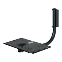
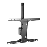
A 170-1033 170-2033 170-4033 1 31" support tray
B 170-1034 170-2034 170-4034 1 27" cross arm
C 170-1035 170-2035 170-4035 1 22" wall support arm
D 170-1036 170-2036 170-4036 2 tilt adjuster gusset
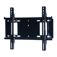
E 170-1039 170-2039 170-4039 1 11" wall bracket
F 590-1005 9PT-66SW02P 590-4005 2 bushing
G 590-1007 6PT-66XX02P 590-4118 1 retainer plug
H 560-9643 560-9643 560-9643 1 retainer pin
I 590-1053 590-1054 590-4053 2 cross arm endcap
J 1545-275 1545-285 1545-265 1 retainer strap
K 520-9400 5S2-M08-H71 5S2-M08-H71 1 M8 x 70 mm bolt
L 520-9250 520-2005 520-2005 4 M5 x .8 x 10 mm pan screw
M 1545-274 9PT-99XX02P 9PT-99XX02P 1 draw bar
N 520-9270 520-9278 520-9278 2 M6 x 16 mm screw bolt
O 520-1023 520-9406 520-9406 2 M5 x .8 x 6 mm pan screw
P 560-9640 560-9640 560-9640 1 5 mm allen wrench
Q 5S1-015-C03 5S1-015-C04 5S1-015-C04 3 #14 x 2.5 hex screw
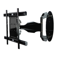
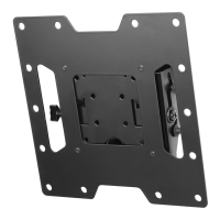
Installation and Assembly - Designer Series TV Wall
Mount for 32" TV's
Model: DS 32, DS 32-SV,
DS 32W
IMPORTANT! Read entire instruction sheet before you start installation and assembly.
Parts List
B
A
E
I
F
H
G
J
D
Q
Before you start make sure all parts listed are included with your product.
Fasteners
N
L
O
C
K
M
M A X I M U M L O A D C A P A C I T Y
MODEL NUMBER MAX WEIGHT OF TV
DS 32, DS 32-SV, DS 32W 160 lbs. (73 kg.)
R
This product is intended for use with UL
Listed products and must be installed by a
qualified professional installer.
P