13
C. VENT PIPING & CHIMNEY
1. Inspect the existing chimney or vent system. Make
sure it is in good condition. Inspect chimney liner
and repair or replace if necessary.
2. The vent system and installation must be in
accordance with Venting of Equipment chapter of
the current edition of the National Fuel Gas Code,
ANSI Z223.1/NFPA 54, sections 7.2, 7.3 or 7.4
of CAN/CSA B149.1, Natural Gas and Propane
Installation Code, or applicable provisions of the
local building codes.
3. Chimney/Vent Operation: The vent system must be
sized and installed to provide the draft needed to
remove all combustion products. If the vent system
does not provide enough draft, combustion products
will spill into the building from the draft hood
relief opening. If spillage of combustion products
occurs, check the vent system, the combustion and
ventilation openings and make sure the boiler room
is never under negative pressure.
4. Chimney flue gas condensation is affected by a
number of factors such as chimney design, flue
connector length, common venting, and flue gas
temperature. If your application experiences flue
gas condensation, installation of a listed corrosion
resistant metal liner is required.
5. Inspect the existing chimney and lining for structural
soundness, corrosion and perforations.
6. Do not alter boiler draft hood or place any
obstruction or non-listed damper in the vent system.
7. Install vent pipe to slope upward at least 1/4” per
lineal foot (21 mm per meter) between the draft
hood outlet and the chimney.
Installer le tuyau d’évent avec une pente ascendante
minimum de 21 mm au mètre (1/4 po au pied) à la
sortie du coupe-tirage et la cheminée.
8. Before connection of joints, inspect the vent pipe
interior for foreign objects such as tools, equipment,
rags, etc. and remove if present.
9. Insert vent pipe into but not beyond the inside wall
of the chimney flue.
10. Do not connect vent connectors serving appliances
vented by natural draft into any portion of mechanical
draft systems operating under positive pressure.
11. Support horizontal portions of the venting system
to prevent sagging by use of metal strapping or
equivalent means. Locate supports at no more than
4 foot (1.2 meter) intervals.
Fournir un support à toute portion horizontale du
système d’évacuation à l’aide de courroies de métal
ou une méthode équivalente afin de l’empêcher de
s’affaisser. Placer les supports à des intervalles ne
dépassant pas cent vingt deux (122) centimètres
(4 po), ou en suivant les recommandations d’
installation du fabricant.
12. Secure all joints including flue collar, draft hood,
vent damper, using sheet metal screws or per listed
vent manufacturer’s instructions.
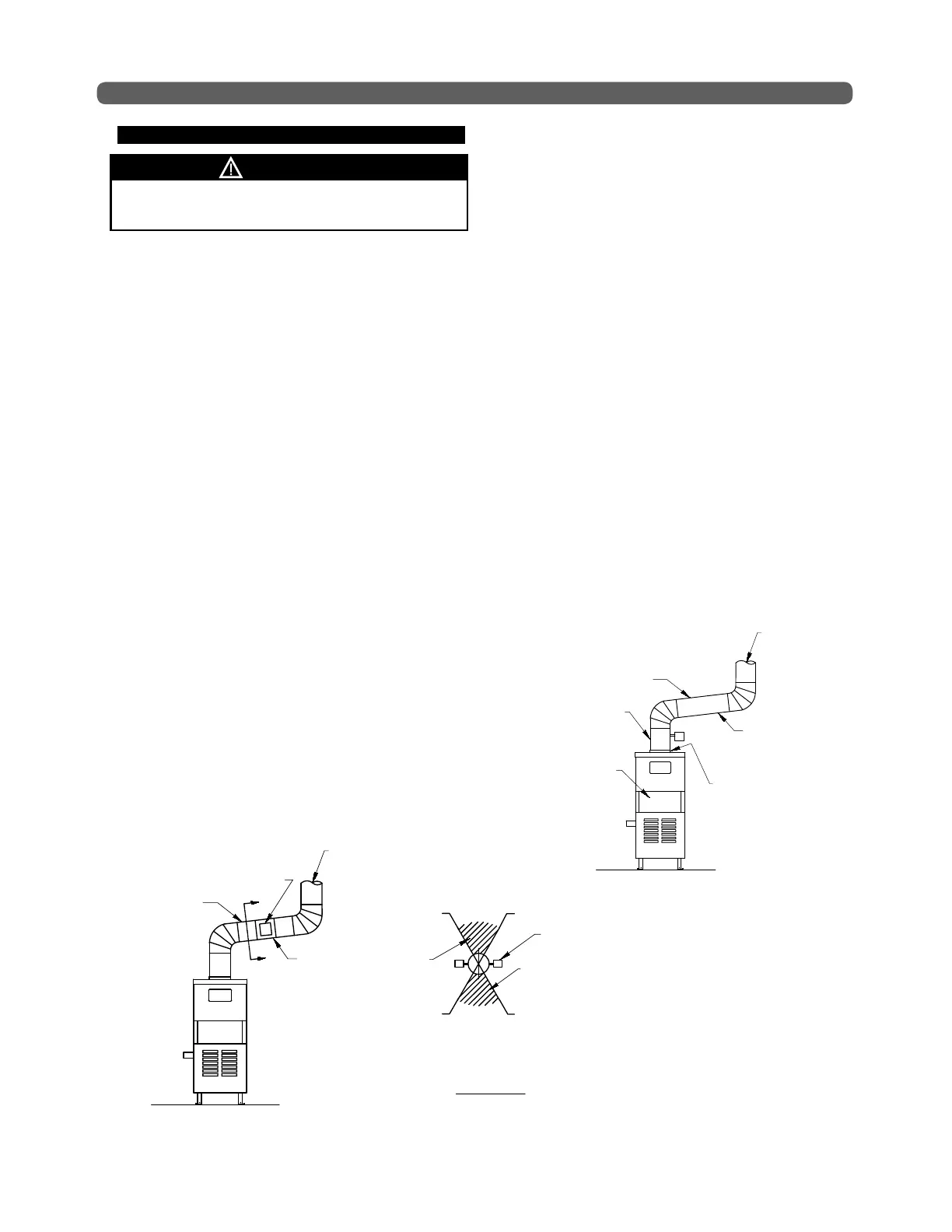
VENTING
Figure 4.3: Venting with Vent Damper in Horizontal Position
1 O'CLOCK
POSITION
5 O'CLOCK
POSITION
7 O'CLOCK
POSITION
11 O'CLOCK
POSITION
HEAT
ZONE
CONDENSATION
ZONE
A
A
DO NOT MOUNT DAMPER
OPERATOR IN SHADED REGION
DAMPER
OPERATOR
SLOPE UP
A MINIMUM
OF 1/4"
PER FOOT
(21mm
PER METER)
VENT
DAMPER
SECTION A-A
VENT TO
CHIMNEY
SUPPORT AS
REQUIRED
Failure to follow all instructions can result in flue gas
spillage and carbon monoxide emissions.
WARNING
DRAFT
HOOD
RELIEF
OPENING