21
A. COMPLETING THE INSTALLATION
1. Confirm that all water, gas and electricity are
turned off.
2. Inspect the boiler combustion chamber for foreign
objects and remove if present.
3. Check physical condition of burners and pilot.
Make certain that there are no unusual bends
or perforations in the burners or pilot. Replace
components if necessary.
4. Verify that water piping, venting, gas piping and
electrical wiring and components are installed
properly. Refer back to previous sections of these
instructions as well as equipment manufacturer’s
instructions as necessary.
5. Set the air pressure on the expansion tank to the
system water pressure before filling system. The
pressure reducing valve on the fill line will typically
allow the system to be filled and pressurized to
12 psi (83 kPa). Consult the valve and expansion
tank manufacturer for more specific information.
6. Fill the boiler and system with water making certain
to vent air from all high points in the system. Water
should bleed from each air vent when it is opened.
7. See Section 1 - Preinstallation for boiler water
treatment requirements.
8. Check joints and fittings throughout the system for
leaks. If leaks are found, drain the system and repair
as required.
9. Connect a manometer to the gas valve on the valve
outlet (gas manifold). Use the 1/8 NPT tapping
provided.
10. Confirm that the gas supply pressure to the boiler is
above the minimum and below the maximum values
for the gas being used. See the end of Section 5 for
these values. If a supply pressure check is required,
isolate the boiler and gas valve before performing
the pressure check. If the supply pressure is too high
or too low, contact the gas supplier.
11. Turn on electricity and gas to boiler.
12. Light the boiler by following the Lighting/Operating
Instructions label mounted to the jacket panel.
Operating Instructions are also shown in Figures 7.5
thru 7.8. The initial ignition may require several tries
as the piping is purged of air.
13. Use the sequence description in Figure 6.6 in
Section 6 (Electrical) to follow light-off and shutdown
sequences and to assist in diagnosing problems. If
the boiler does not function properly, consult Section
8, Troubleshooting.
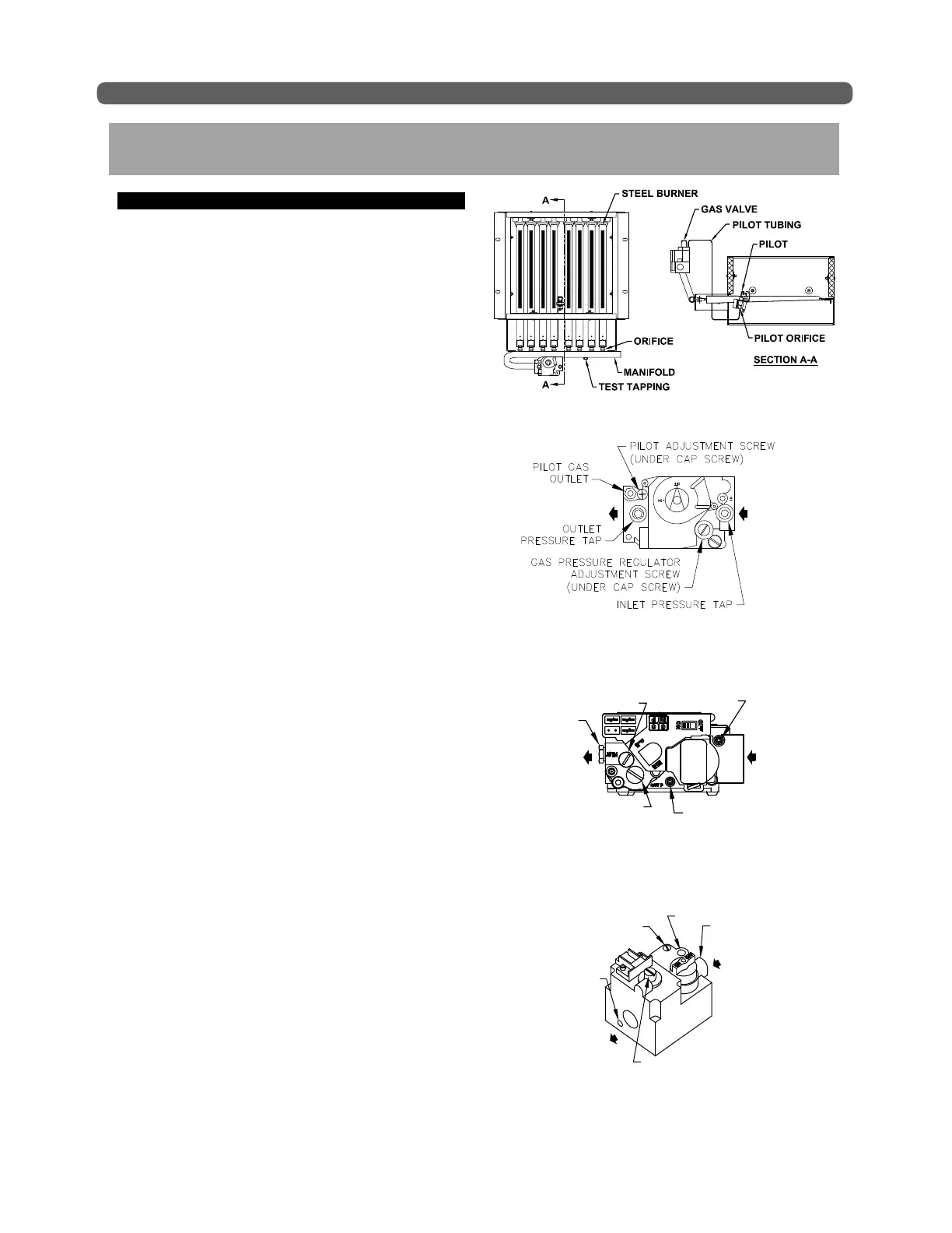
14. The gas manifold and control assembly are made of
gas-tight, completely factory assembled and installed
components of the base assembly. See Figure 7.1.
START-UP PROCEDURES
7. START-UP PROCEDURES
Figure 7.1: Gas Valve, Manifold and Burner
Assembly
Figure 7.2: Valve Tapping and Adjustment Screw
Locations, Residio Gas Valve
OUTLET INLET
Figure 7.4: Valve Tapping and Adjustment Screw
Locations, Robertshaw Gas Valve
OUTLET
GAS PRESSURE REGULATOR
ADJUSTMENT SCREW
(UNDER CAP SCREW)
INLET
PILOT GAS OUTLET
PILOT ADJUSTMENT
SCREW (UNDER
CAP SCREW)
OUTLET
PRESSURE
TAP
INLET
PRESSURE
TAP
Figure 7.3: Valve Tapping and Adjustment Screw
Locations, White Rodger Gas Valve
OUTLET
INLET
PRESSURE
TAP
GAS PRESSURE
REGULATOR
ADJUSTMENT SCREW
(UNDER CAP SCREW)
INLET
OUTLET
PRESSURE
TAP
PILOT GAS
OUTLET
PILOT
ADJUSTMENT SCREW
(UNDER CAP SCREW)