15
A. WIRING
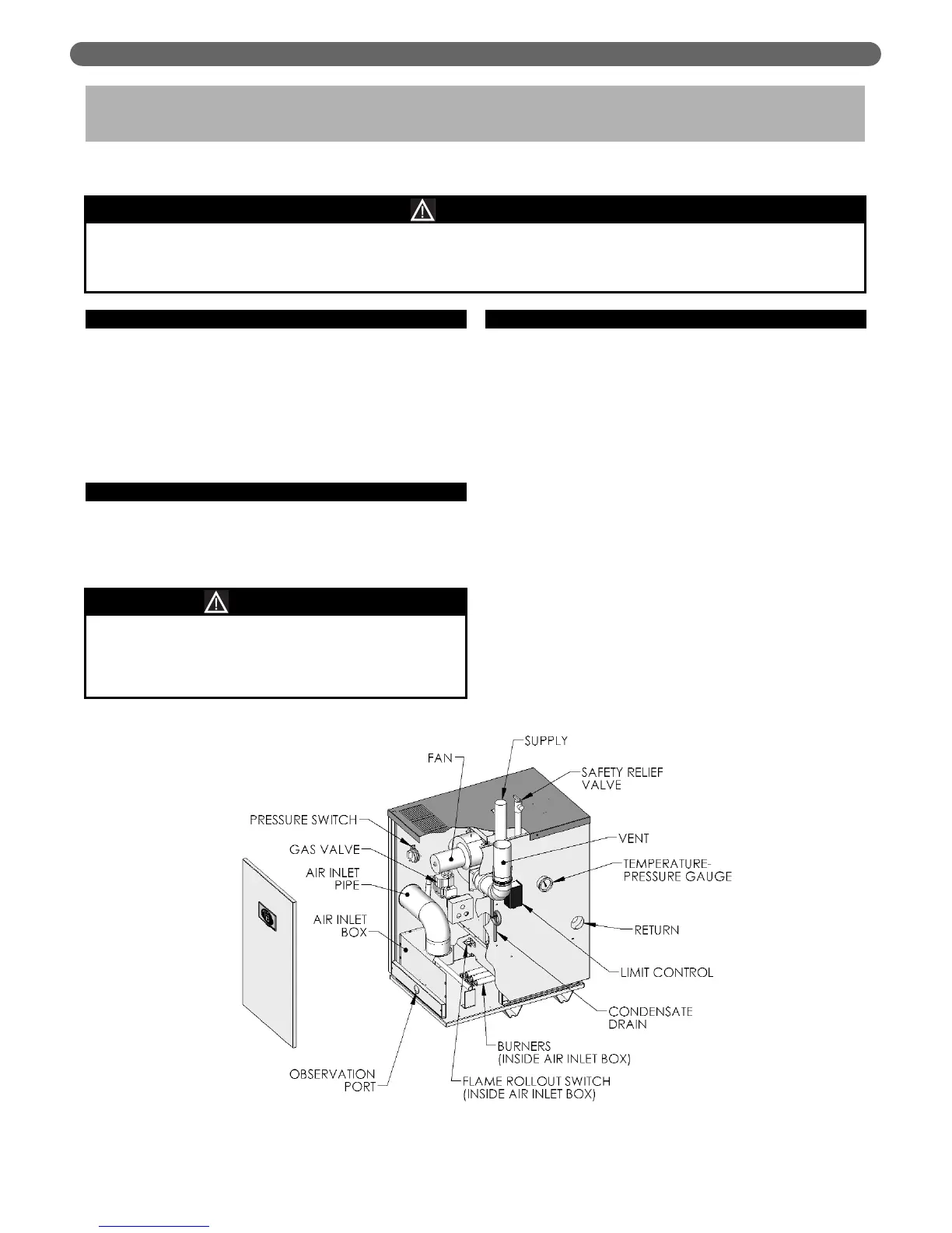
1. See Figure 6.1 for location of wiring and controls. Use
Figure 6.2 to connect the boiler to a power supply
and to connect components to the boiler.
2. Connect the boiler by a separate, permanently live
electrical supply line with a fused switch.
3. Adjust the thermostat heat anticipator to 0.2 Amp.
B. ZONED SYSTEM WIRING
See Figure 6.4 for typical wiring with zone valves. See
Figure 6.5 for typical wiring with zone circulators. When
wiring a zoned heating system, follow all applicable
codes, ordinances and regulations.
C. CONTROLS
1. For proper location of controls and accessories refer to
Figure 6.1.
2. See the attached control sheets for specific details
regarding the installation of the various controls.
3. This boiler is supplied with safety devices in addition
to the limit. For a description of these devices and
how they work to ensure the safe operation of the
boiler, see Section 7.
4. If the circulator is mounted in the supply piping,
provide longer wiring harness as required.
ELECTRICAL
6. ELECTRICAL
This unit when installed must be electrically grounded in accordance with the requirements of the authority
having jurisdiction or, in the absence of such requirements, with the current edition of the
National Electrical
Code,
ANSI/NFPA 70 and/or the
Canadian Electrical Code
, Part 1, CSA C221.
NOTICE
Figure 6.1: Wiring, Controls and Safety Devices
Install all electrical wiring in accordance with the National Electrical Code and local requirements.
Do not power zone valves directly from the boiler
transformer. Doing so will greatly reduce the life of
the transformer. Use a separate transformer sized to
handle the total of all zone valve electrical loads.
NOTICE