3. WATER PIPING AND CONTROLS
r,_! I :{e] II! =i:!_'tl J;j "Jk'm,__ _ I w]l ; I =ilI[I J;1h_
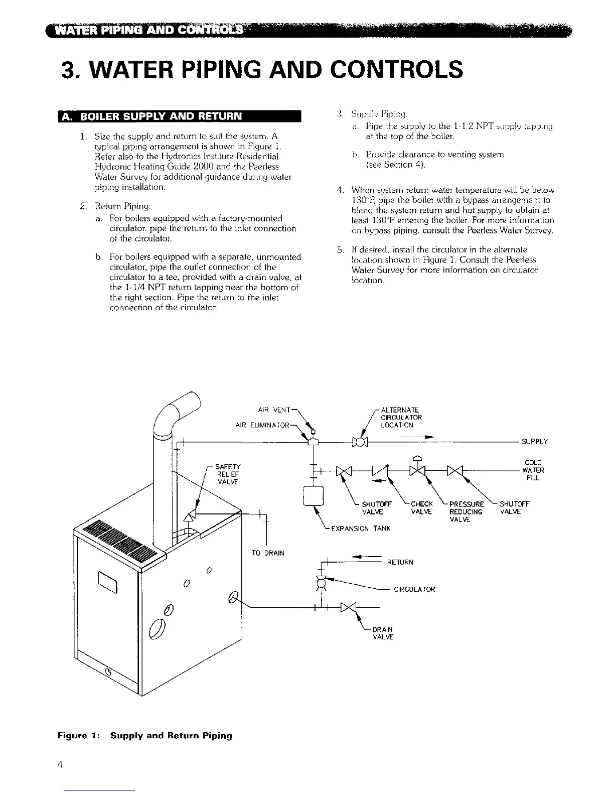
]. Size the supply and return to suit the system. A
typical piping arrangement is shown in Figure i.
Refer also to the Hydronics Institute Residential
Hydronic Heating Guide 2000 and the Peerless
Water Survey for additional guidance during water
piping installation.
2 Return Piping:
a. For boilers equipped with a factory-mounted
circulator, pipe the return to the inlet connection
of the circulator.
b For boilers equipped with a separate, unmounted
circulator, pipe the outlet connection of the
circulator to a tee, provided with a drain valve, at
the 1-1/4 NPT return tapping near the bottom of
the right section Pipe the return to the inlet
connection of the circulator
3
4.
5.
Supply Piping:
a Pipe the supply to the I I 2 NPT supply tapping
at the top of the boiler.
b Provide clearance to venting system
(see Section 4)
When system return water temperature will be below
130°F, pipe the boiler with a bypass arrangement to
blend the system return and hot supply to obtain at
least 130°F entering the boiler. For more information
on bypass piping, consult the Peerless Water Survey
If desired, install the circulator in the alternate
location shown in Figure I. Consult the Peerless
Water Survey for more information on circulator
location
AIR VENT_
AIR ELIMINATOR _
-- SAFETY
RELIEF
VALVE
)_-ALTERNATE
CIRCULATOR
LOCATION
SUPPLY
COLD
WA1ER
NLL
SHUTOFF
VALVE VALVE" REDUCING VALVE
VALVE
_-EXPANStON TANK
0
o
©
TO DRAIN
RE_JRN
CIRCULATOR
DRAIN
VALVE
Figure 1: Supply and Return Piping