24
1. Do not install any piping directly in front of the boiler
or along either side. Always provide access to the
front cover and side panel openings.
2. Install a sediment trap as shown in Figure 5.1. Be sure
to allow clearance from the floor or other horizontal
surface for removal of the pipe cap.
* Natural gas input rates are based on 1,000 Btu/ft
3
, LP input
rates are based on 2,500 Btu/ft
3
.
3. Install a ground joint union between the sediment trap
and the boiler to allow service to the appliance.
4. Install a service valve as shown in Figure 5.1 to allow
the gas supply to be interrupted for service.
5. Maintain a minimum distance of 10 pipe diameters
between the gas pressure regulator and the boiler.
6. Check all gas piping for leaks prior to placing the
boiler in operation. Use an approved gas detector,
non-corrosive lead detection fluid, or other leak
detection method. If leaks are found, turn off gas flow
and repair as necessary.
7. Figure 5.1 shows the gas shutoff valve for the Series
PBC™ boiler. This valve is to be used in addition to
the gas service valve shown upstream of the sediment
trap.
D. GAS SUPPLY PIPING - OPERATION
1. The gas line must be properly purged of air to allow
the boiler to operate properly. Failure to do so may
result in burner ignition problems.
2. Table 5.3 shows the maximum and minimum fuel gas
supply pressure to be measured at the gas valve inlet
pressure tap. See figure 5.2.
a. Gas pressure below 3.5 inches of water column for
Natural gas and 8 inches of water column for LP
gas may result in ignition failures and hard
ignitions.
b. Gas pressure above 13.5 inches of water may
result in damage to the automatic gas valve.
3. To check the gas supply pressure to the gas valve:
a. Turn off the power at the service switch.
b. Close the gas shutoff valve.
c. Using a flat screwdriver, turn the screw inside the
inlet tap fitting (see Figure 5.2) one turn counter
clockwise.
d. Attach the tube from the manometer to the
pressure tap fitting.
e. Open the gas valve and start the boiler.
f. Read and record the gas pressure while the boiler
is firing at max input as well as with any other
appliances to the same gas line at their maximum
inputs.
g. Turn off the boiler and close the gas shutoff valve.
h. Remove the manometer tube from the pressure
tap fitting.
i. Turn the internal screw clockwise to close the
valve.
j. Turn on the gas shutoff valve and boiler service
switch.
k. Fire the boiler and check for fuel gas odor around
the gas valve. If an odor is evident check to make
sure that the pressure tap fitting is closed.
4. All gas piping must be leak tested prior to placing the
boiler in operation.
a. If the leak test pressure requirement is higher than
13.5 inches of water column, the boiler must be
isolated from the gas supply piping system.
b. If the gas valve is exposed to pressure exceeding
13.5 inches of water column, the gas valve must
be replaced.
5. Install the boiler such that the gas ignition system
components are protected from water (dripping,
spraying, rain, etc.) during operation and service
(circulator replacement, condensate collector and
neutralizer cleanout, control replacement etc.)
E. MAIN GAS VALVE - OPERATION
1. Figure 5.2 is an illustration of the gas valve/venturi
assembly for the Series PBC™ boiler.
a. Adjustments should not be made to the gas valve
without instrumentation to measure carbon
dioxide (CO
2
) and carbon monoxide (CO)
emissions in the vent pipe.
b. Turning the throttle screw clockwise will decrease
the gas flow (decreasing CO
2
) and turning it
counterclockwise will increase the gas flow rate
(increasing CO
2
). Markings adjacent to the throttle
screw show + and – indicating this operation.
c. The recommended CO
2
settings are given in Table
5.4. In no case should the boiler be allowed to
operate with CO emissions above 200 ppm.
FUEL PIPING
When checking for leaks, do not use matches,
candles, open flames or other methods that provide
an ignition source. This may ignite a gas leak
resulting in a fire or explosion.
WARNING
Do not subject the gas valve to more that 1/2 psi
(13.5" W.C.) of pressure. Doing so may damage the
gas valve.
CAUTION
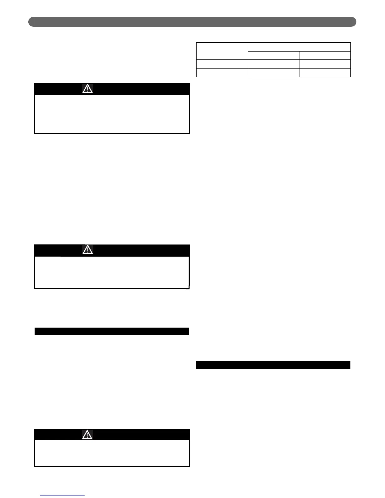
Fuel Type
Pressure Inches W.C. (Pa)
Minimum Maximum
Natural Gas 3.5 13.5
LP Gas 8 13.5
Table 5.2: Maximum and Minimum Fuel Pressure
Use a pipe joint sealing compound that is resistant to
liquefied petroleum gas. A non-resistant compound
may lose sealing ability in the presence of this gas,
resulting in a gas leak. Gas leaks may potentially
cause an explosion or fire.
WARNING