16
A. GENERAL
1. Size water supply and return piping in accordance
with system requirements rather than the boiler
connections.
2. If the Series PBC™ boiler is used to replace an existing
boiler, make sure the system piping is thoroughly
cleaned and free from debris before installing this boiler.
Sentinel Performance Solutions (http://www.sentinel-
solutions.net/us/) offers a full line of cleaners (X300),
sludge remover (X400), antifreeze (X500) and
corrosion inhibitors (X100/X500) for hydronic
applications.
3. In hydronic systems where sediment may exist, install
a strainer in the boiler return piping to prevent large
particles and pipe scale from entering the boiler heat
exchanger. Use a large mesh screen in the strainer.
4. Install this boiler so that the gas ignition system
components are protected from water (dripping, spraying,
etc.) during operation and service (circulator replacement,
condensate trap cleaning, sensor replacement, etc.).
5. The Series PBC™ heating boiler is intended for use in
a closed-loop hydronic system. Leaks in the piping
system may require constant make-up water which
may include oxygen, calcium and other substances
which may cause corrosion, calcium scale buildup, or
other attacks on the hydronic system piping. The
system water should have a pH value of between 8.2
and 9.5. The water hardness is to be maintained
between 50 ppm CaCO
3
(3 gr/gal) and 150 ppm
CaCO
3
(9 gr/gal). Also, a minimum water pressure of
14.5 psi is required for proper performance.
B. OPERATING PARAMETERS
1. The Series PBC™ boiler is designed to operate in a
closed loop hydronic system under forced circulation.
This requires the system to be completely filled with
water and requires a minimum water flow through the
boiler to operate effectively.
2. The minimum system pressure is 11.6 psig (80 kPa).
The maximum allowable pressure is 40 psig (275 kPa).
3. The recommended minimum system pressure for
optimal operation at higher temperature is 14.5 psi
(100kPa).
4. The internal pump is sized appropriately to allow for
the minimum flow rate required through the heat
exchanger. Ensure that the piping up to the boiler is
capable of handling a minimum flow rate of 5.0 GPM
to allow for proper flow rates when the boiler is in
CH mode.
C. SYSTEM COMPONENTS
Figure 4.1 shows the symbol key for piping diagrams in
this section. The following are brief descriptions of system
components.
1. Pressure/Temperature Gauge: A combination
pressure/temperature gauge is provided with each
Series PBC™ boiler to be mounted in the piping from
the boiler supply to the system as shown in Figures
4.2 & 4.3. Most local codes require this gauge.
2. Air Elimination: Closed loop hydronic systems require
air elimination devices. As the system water is heated,
dissolved oxygen and other gases will separate from
the liquid. An air elimination device (such as a TACO
Vortech
®
Air Separator) is required to remove the
dissolved gases preventing corrosion in the piping
system and eliminating noise.
3. Expansion Tank: An expansion tank (such as a Bell &
Gossett Series HFT) is required to provide room for
expansion of the heating medium (water or glycol
solution). Consult the expansion tank manufacturer's
instructions for specific information regarding
installation. The expansion tank is to be sized for the
required system volume and capacity. In addition, be
sure that the expansion tank is sized based on the
proper heating medium. Glycol solutions may expand
more than water for a similar temperature rise.
WATER PIPING AND CONTROLS
4. WATER PIPING & CONTROLS
Use only inhibited propylene glycol solutions which
are specifically formulated for hydronic systems.
Unlike automotive antifreeze, solutions for hydronic
applications contain corrosion inhibitors that will
protect system components from premature failure
due to corrosion.
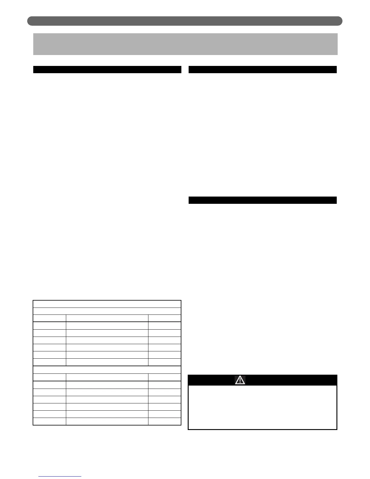
CAUTION
Maximum Flow Rates and Input
Steel Pipe
Pipe Size Maximum Flow (GPM) BTU/HR
1/2"
2 15,000
3/4"
4 40,000
1"
8 80,000
1-1/4"
16 140,000
1-1/2"
25 220,000
2"
50 450,000
Copper Tubing
Tube Size
Maximum Flow (GPM) BTU/HR
1/2"
1.50 15,000
3/4"
4 40,000
1"
8 80,000
1-1/4"
14 140,000
1-1/2"
22 220,000
2"
45 450,000
Table 4.1: Guide of Maximum Flow Rates for
Different Pipe Sizes with Input