44
TROUBLESHOOTING
A. LOCKOUT ERRORS
1. When a lockout error occurs the display will show
“Loc” followed by a number code.
2. Lockout codes require that the control be manually
reset either by holding the center reset button on the
display or by pressing the reset button on the main
control board itself.
3. Lockout errors should be investigated further to
determine the cause of the by a qualified service
technician.
B. BLOCKING ERRORS
1. When a blocking error occurs the display will show
“Err” followed by a number code.
2. Blocking errors will automatically clear if the condition
is corrected.
3. These error messages and some suggested actions are
listed in Table 10.2
C. WARNING ERRORS
1. When a warning error occurs the boiler display will
“Atte” followed by a number code.
2. Warning errors are a will automatically clear once the
condition is corrected and will not prevent the boiler
from operating.
3. Warning 204 is for Outdoor Sensor not Connected.
The Series PBC™ units will display this warning on
start-up if the provided outdoor sensor is not
connected.
D. TYPICAL OPERATION CYCLE –
CENTRAL HEAT
1. Boiler is in standby. No demand. Central Heat
Radiator symbol is constant.
2. Demand is applied. Central Heat Radiator symbol
begins flashing
3. Switching valve stepper motor extends to Central heat
position, boiler pump and CH pump start
4. Blower begins Pre-purge for 7 seconds at ignition
speed.
5. Spark engages 2 seconds
6. Gas valve opens.
7. Spark remains engaged for 2 more seconds.
8. Two second flame proving period holds valve open
while control checks for flame signal
9. Boiler holds at ignition speed for 10 seconds before
modulation begin.
10. Demand is met and removed.
11. Gas valve closes, Fan returns to ignition speed.
12. 10 second post purge period.
13. Switching valve returns to DHW position.
14. Pumps remain energized for pump post purge period.
15. Full unit standby
E. TYPICAL OPERATION CYCLE – DHW
1. Boiler is in standby. No demand. Domestic Faucet
symbol is constant.
2. Demand is applied when flow sensor detects hot
water flow. Domestic Faucet symbol begins flashing
3. Boiler pump starts
4. Blower begins Pre-purge for 7 seconds at ignition
speed.
5. Spark engages 2 seconds
6. Gas valve opens.
7. Spark remains engaged for 2 more seconds.
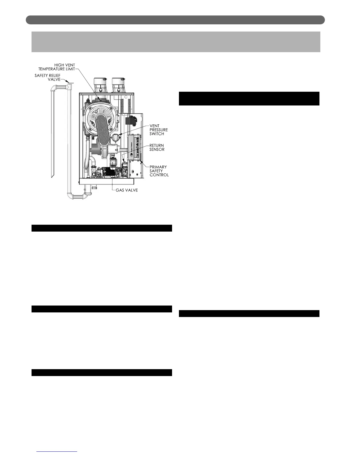
10. TROUBLESHOOTING
Figure 10.1: Additional Safety Locations