45
8. Two second flame proving period holds valve open
while control checks for flame signal
9. Boiler holds at ignition speed for 10 seconds before
modulation begin.
10. Demand is met and removed.
11. Gas valve closes, Fan returns to ignition speed.
12. 10 second post purge period.
13. Pump remain energized for pump post purge period.
14. Full unit standby
TROUBLESHOOTING
If overheating occurs or the gas supply fails to shut
off, do not turn off electrical power to the circulating
pump. This may aggravate the problem and increase
the likelihood of boiler damage. Instead, shut off the
gas supply to the boiler at the gas service valve.
CAUTION
DANGER
When servicing or replacing components that are in
direct contact with the boiler water, be certain that:
• There is no pressure in the boiler. (Pull the release
on the relief valve. Do not depend on the pressure
gauge reading).
• The boiler water is not hot.
• The electrical power is off.
When servicing or replacing any components of this
boiler be certain that:
• The gas is off.
• All electrical power is disconnected.
WARNING
Do not use this appliance if any part has been under
water. Improper or dangerous operation may result.
Contact a qualified service technician immediately to
inspect the boiler and to repair or replace any part of
the boiler which has been under water.
WARNING
Label all wires prior to disconnection when servicing
controls. Wiring errors may cause improper and
dangerous operation. Verify proper operation after
servicing.
CAUTION
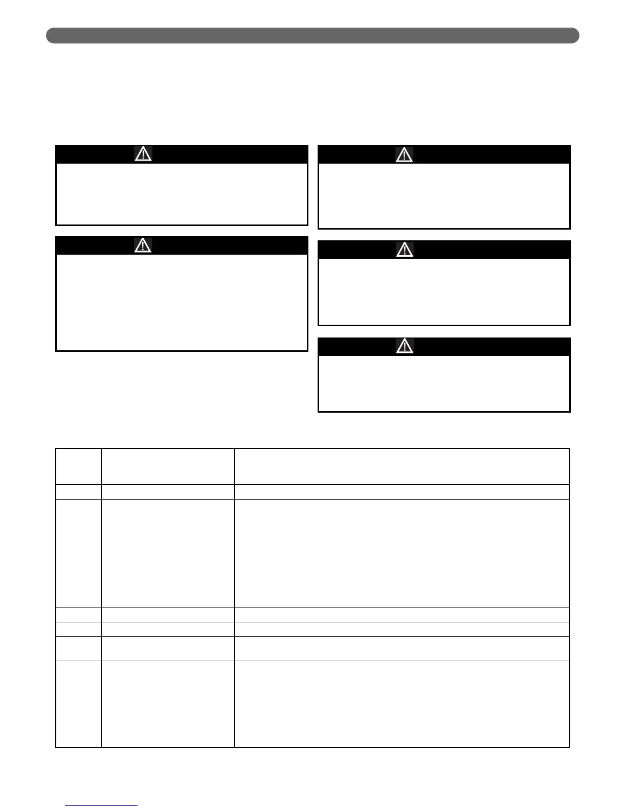
Table 10.1: Lockout Codes
Error
Number
Error Display Corrective Action
0 E2PROM_READ_ERROR
Internal Software error. Replace control.
1 IGNIT_ERROR
Three unsuccessful ignition attempts in a row.
–
Check for spark by ear. Also check for 120V across the blue and brown control output wire
to the spark module. If not spark is present but voltage is. Replace module. If no voltage is
present check parameter 2126. Should be set to 9. If setting is correct, replace control.
–
Remove flame sensor and check for white build-up. Clean sensor, re-install and attempt
ignition. If ignition still fails perform other actions listed here. Replace sensor. If sensor
appears cracked or bent, replace sensor.
–
Confirm fuel pressure at the valve inlet when the valve is open. Low gas pressure can
cause ignition failures. High gas pressure can cause the valve to not operate and or
damage the valve.
2 GV_RELAY_ERROR
Failure detected in the Gas Valve Relay. Replace Control
3 SAFETY_RELAY_ERROR
Failure detected in the safety relay. Replace Control.
4 BLOCKING_TOO_LONG
Blocking error present for more than 20 hours.
–
Go to parameter 1052 for last blocking error code. Correct cause.
5 FAN_ERROR_NOT_RUNNING
Fan is not running for more than 60 secs.
–
Check fan condition by disconnecting the 5 pin control plug on the blower. Fan should
ramp to full power when the unit is turned on.
–
If fan does not power on, check for 120 volts across the brown and blue wires in the three
pin connector. If voltage is present, replace blower.
–
If fan powers on check for continuity through blower control harness, 5 pin connector to
J4 connector on control board. If continuity is found replace control. If no continuity is
found, replace harness.