39
J. IGNITION SEQUENCE
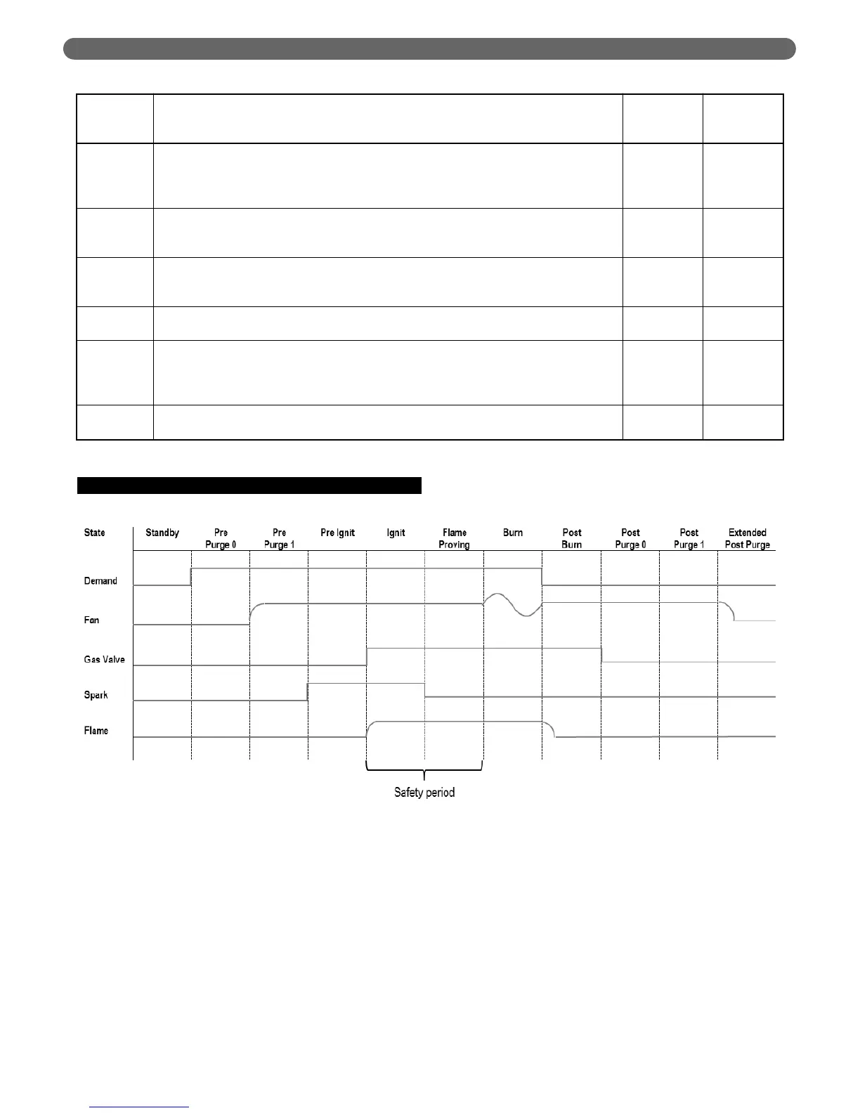
Figure 8.4 shows a typical ignition and burn cycle for the
Series PBC™ boiler. Pre-purge and Post Pure periods are
shown in a compressed fashion to show the ignition
process in detail.
1. Boiler receives a demand either CH or DHW
2. Blower ramps up to ignition speed and hold for Pre-
purge period of 7 seconds
3. Spark is initiated 1 second before gas valve
4. Gas valve opens
5. Gas valve remains open for flame proving period. If
no flame is detected, the gas valve closes and the
blower moves to Post-purge.
6. If flame is detected, the boiler will begin to modulate
to maintain setpoint until the demand is removed.
7. Once demand is removed, gas valve closes and
blower moves to Post-purge for 10 seconds.
8. After Post-purge, blower shuts down and awaits next
demand.
Table 8.8 (cont.): Outdoor Reset Parameters
Status
(2000)
Parameters
Parameter Function
Unit/Value
Default
Options
2022
Mild Weather Design Outdoor Temperature
–
Sets the Outdoor Temperature at which the boiler will target the Boiler Mild Weather Design
Temperature.
–
For default: Boiler will target 104°F when the outdoor temperature is 68°F.
°F 68
2023
Minimum CH Setpoint
–
Design Supply minimum (limit)
–
Sets lower limit of Calculated CH setpoint
–
Calculated CH setpoint will always be at or above this value
°F 190
2024
Maximum CH Setpoint
–
Design Supply Maximum (limit)
–
Sets upper limit of Calculated CH setpoint
–
Calculated CH setpoint will always be at or below this value
°F 68
2025
Warm Weather Shutdown Temperature
–
Outdoor temperature that will block all CH demands until temperature falls below this value
°F 72
2026
Boost Function: Increment
–
Calculated Setpoint increase after boost delay time period is met
–
Boost will continually increase setpoint every boost time period until demand is met or
Maximum CH Setpoint design limit is reached.
°F 5
2027
Boost Function: Delay
–
Time delay before boost function activates during a single demand
Minutes 20
BOILER CONTROL: INTERNAL WIRING & OPERATION
Figure 8.4: Ignition Sequence