9
C. EXHAUST VENT/AIR INTAKE PIPE
LOCATION
1. Install vent piping before installing water, fuel, or
condensate piping. Working from largest to smallest
diameter reduces the complexity of piping
interferences.
2. Vent and air intake piping is to be installed so that
there is sufficient access for routine inspection as
required in Section 11, of this manual.
3. The vent piping for this boiler is approved for zero
clearance to combustible construction. However, a fire
stop must be used where the vent pipe penetrates
walls or ceilings.
4. The Peerless
®
Series PBC™ boiler, like all high
efficiency, gas-fired appliances, is likely to produce a
vapor plume due to condensation. Surfaces near the
vent termination will likely become coated with
condensation.
5. Air Intake Pipe Location – Sidewall Venting:
a. Provide 1 foot (30 cm) clearance from the bottom
of the air intake pipe to the level of maximum
snow accumulation. Snow removal may be
necessary to maintain clearances.
b. Do not locate air intake pipe in a parking area
where machinery may damage the pipe.
c. Maintain a minimum of 8" horizontal distance
between exhaust vent and the air intake.
Increasing this distance minimizes the potential for
contamination of the inlet air with exhaust.
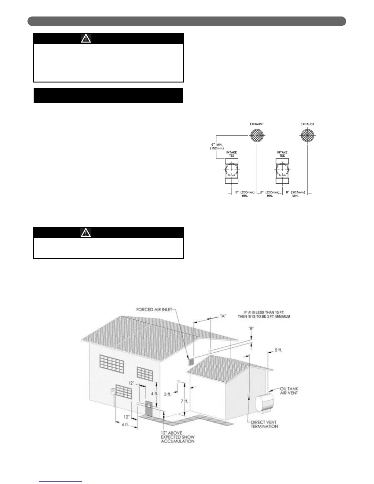
d. For multiple boiler installations, the minimum
horizontal distance between the inlet of one boiler
to the exhaust of an adjacent boiler is 8" center-to-
center. In addition, the minimum vertical distance
between the exhaust and air inlet is 6". See Figure
3.2 for an illustration.
e. The exhaust outlet of the vent pipe should not be
angled any more than 5º from horizontal.
f. Precautions should be taken to prevent
recirculation of flue gases to the air inlet pipe of
the boiler or other adjacent appliances.
7. Sidewall Venting Configuration:
a. See Figure 3.3 for an illustration of clearances for
location of exit terminals of direct-vent venting
systems.
VENTING & AIR INLET PIPING
Figure 3.3: Exit Terminal Location for Mechanical Draft and Direct-Vent Venting Systems
If the maximum equivalent vent length is exceeded,
the maximum burner input rate may be reduced.
NOTICE
Use of cellular core PVC (ASTM F891), cellular core
CPVC, or Radel
®
(polyphenolsulphone) for exhaust
vent is prohibited. Use of these materials as exhaust
vent may result in severe personal injury, death, or
major property damage.
WARNING
Figure 3.2: Vent Pipe Spacing for Multiple Series
PBC™ Boilers