10
• This boiler vent system shall terminate at least
3 feet (0.9 m) above any forced air inlet
located within 10 ft (3 m). Note: This does not
apply to the combustion air intake of a direct-
vent appliance.
• Provide a minimum of 1 foot (30 cm) distance
from any door, operable window, or gravity
intake into any building.
• Provide a minimum of 1 foot (30 cm) clearance
from the bottom of the exit terminal above the
expected snow accumulation level. Snow
removal may be required to maintain clearance.
• Provide a minimum of 4 feet (1.22 m)
horizontal clearance from electrical meters, gas
meters, gas regulators, and relief equipment. In
no case shall the exit terminal be above or
below the aforementioned equipment unless
the 4 foot horizontal distance is maintained.
• Do not locate the exhaust exit terminal over
public walkways where condensate could drip
and create a hazard or nuisance.
• When adjacent to public walkways, locate the
exit terminal at least 7 feet above grade.
• Do not locate the exhaust termination directly
under roof overhangs to prevent icicles from
forming or recirculation of exhaust gases from
occurring.
• Provide 3 feet clearance from the inside corner
of adjacent walls.
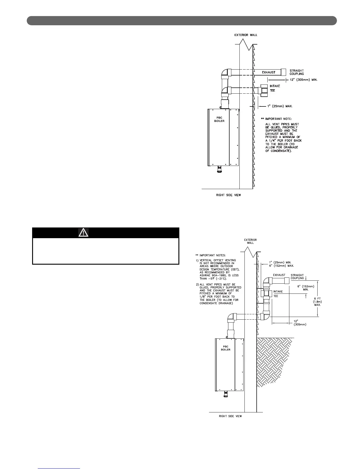
b. Figures 3.4 through 3.7 show approved sidewall
venting configurations using the standard fittings
supplied.
c. Figure 3.5 is only approved for locations in which
the outdoor temperature is above -5°F (-21°C) in
accordance with ASHRAE 90A-1980
recommendations.
d. Figure 3.8 shows approved sidewall vent
configuration using an optional concentric vent
termination kit. 2" (54837) or 3" (54498).
8. Vertical Venting Configuration:
a. Figure 3.9 shows the approved venting
configuration for vertical venting using the
standard fittings supplied.
b. Locate the air intake pipe inlet a minimum of 12"
above the expected snow accumulation on the
roof surface.
c. Locate the end of the exhaust vent pipe a minimum
of 12" above the inlet to the air intake pipe.
d. Figure 3.10 shows an approved vertical vent
configuration using the optional concentric vent
termination kit.
VENTING & AIR INLET PIPING
Figure 3.4: Standard Exhaust & Air Inlet Pipe
Terminations
Figure 3.5: Offset Exhaust and Air Inlet
Terminations
Condensing flue gases can freeze on exterior
building surfaces which may cause discoloration and
degradation of the surfaces.
CAUTION