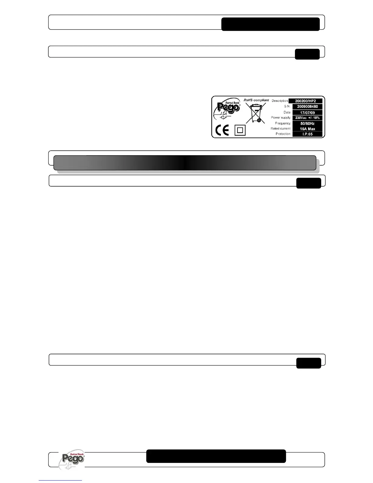
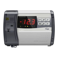
IDENTIFICATION DATA
The unit described in this manual has an ID plate on the side showing all the relevant
identification data:
• Name of Manufacturer
• Code and model of unit electrical board
• Serial number
• Date
• Power supply
• Rated current
• IP protection rating
IMPORTANT INFORMATION FOR THE INSTALLER
1. Install the device in places where the protection rating is observed and try not to
damage the box when drilling holes for wire/pipe seats.
2. Do not use multi-polar cables in which there are wires connected to inductive/power
loads or signalling wires (e.g. probes/sensors and digital inputs).
3. Do not fit power supply wiring and signal wiring (probes/sensors and digital inputs) in
the same raceways or ducts.
4. Minimise the length of connector wires so that wiring does not twist into a spiral shape
as this could have negative effects on the electronics.
5. Fit a general protection fuse upstream from the electronic controller.
6. All wiring must be of a cross-section suitable for relevant power levels.
7. When it is necessary to make a probe/sensor extension, the wires must have a cross-
section of at least 1 mm
2
. Probes extension or shortening could alter their factory
calibration; therefore to check and calibrate the probes through an external thermometer.
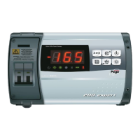
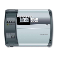
STANDARD ASSEMBLY KIT
For the purposes of assembly and use, the electronic ECP200 BASE control unit comes
with:
• N° 3 seals, to be fitted between the fixing screws and the box back panel
• N° 1 user’s manual.