PV 20a
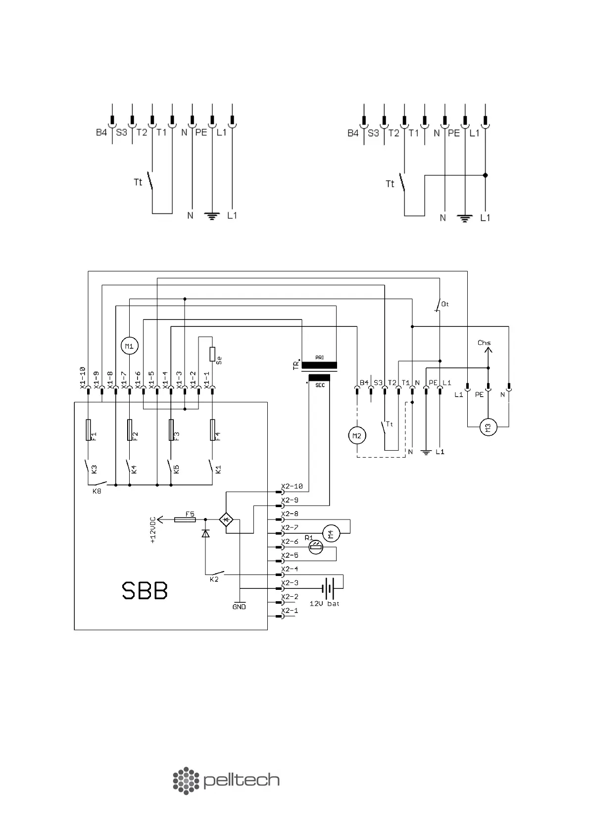
Figure 8 Burner 5-wire connection
Figure 9 Burner 4-wire connection
Chs – Chassis grounder R1 – Flame sensor
M1 – Fan SBB – Controller board
M2 – Flue gas fan* Se – Igniter
M3 – External auger TR – Transformer
M4 – Internal feeder Tt – Boiler thermostat
Ot – Safety thermostat
*Flue gas fan M2 is installed only if there is not enough draught. The flue gas fan is not included with burner.
13 www.pelltech.eu