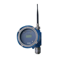
PT395 Series Detector
Transmitter Wiring
Follow steps below for installation.
3. Remove the enclosure cover and un-plug the transmitter board by simply moving
the thumb screws in counter-clockwise direction until they have loosened up.
Slowly pull the transmitter board and detach the ribbon cable. Do not completely
un-screw or remove the thumb screws from the transmitter board.
4. Using a 3 conductor cable connect the termination board with the monitor or
controller as shown in figure 4. A shielded instrumentation cable must be used to
connect the detector to the controller for power and signal output. Refer to the
cable size chart at the end of this section for proper cable.
5. For Audio / Visual alarm connection or Alarm Relay Dry Contact, refer to figure 5
for wiring diagram. Be sure that the power rating of the alarm device does exceed
the Ampere rating of the alarm relay contacts. See relay ratings in the
specification section of the manual.
6.
7. Reconnect the transmitter board with the connection board with the 10 pin ribbon
cable. Mount the transmitter board on two 2 stand-offs using thumb screws on
the board. Note: Do not apply excessive force to tighten the screws.
8.
9. Place the cover back on the enclosure.
Caution: Cable Shield wire should be grounded at the controller or PLC
side not inside the detector enclosure.


 To Next Page