Table 2: A421 Control wiring terminals and wire size information
Terminal
block
Label Description, function, and requirements Wire sizes
LNC Line-voltage SPDT relay normally closed contact: Connects
controlled equipment to the line-voltage normally closed
(LNC) contact on the SPDT relay. When LC is closed to LNC,
the relay is de-energized and the green LED is off. The LNC
terminal is not typically wired to the controlled equipment.
BIN Detects a switch closure between the BIN and COM
terminals and manually starts or stops a defrost cycle. This
is now the default behavior for the binary input.
COM Connects the low-voltage common from the sensor and
binary input.
TB3
SEN Connects the low-voltage input signal wire from control
sensors.
22 AWG (0.34
mm²) stranded,
shielded cable
Setup and adjustments
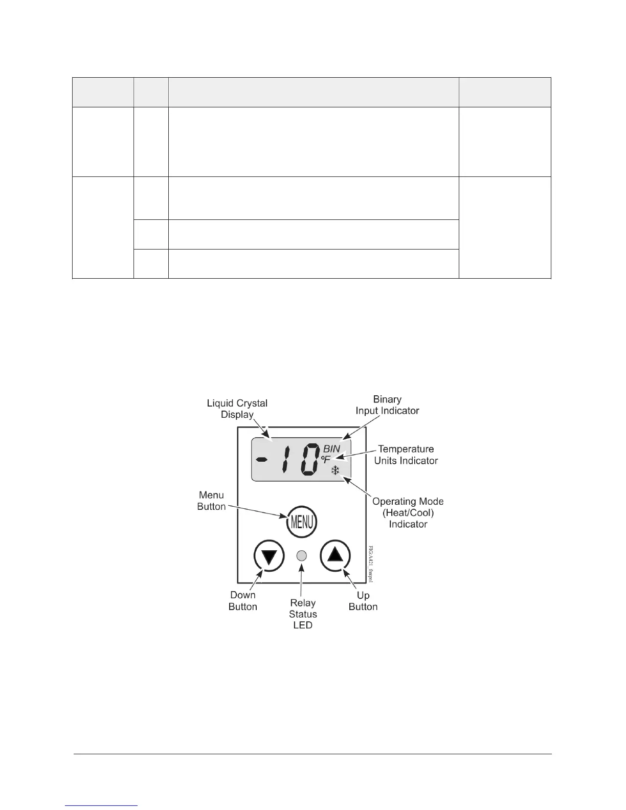
The front panel of the A421 Series Electronic Temperature Control has an LCD and a three-button UI
as shown in the following figure.
Figure 5: A421 Control front panel with LCD and three-button UI
LCD
The A421 Series Control has a backlit LCD screen (Figure 5). You can adjust the LCD brightness.
During normal operation, the LCD displays the Main screen, which provides the following
information:
• Temperature sensed at the A99 sensor
A421 Series Electronic Temperature Controls with Off-Cycle Defrost Installation Guide8
 Loading...