P70, P72, and P170 Series Controls for Dual Pressure Applications Installation Instructions
10
Manual Reset Operation
Pressure controls, with the Manual Reset option, lock out when they reach the cutout pressure setpoint and must
be manually reset by the user to restart the controlled equipment. The manual reset mechanism is trip-free and
cannot be overridden by blocking or tying the reset button down.
On locked-out equipment, first determine and remedy the cause of the lockout before proceeding.
• When lockout is caused by the control’s low side cutout, allow the sensed pressure to rise to the cut in setpoint.
• When lockout is caused by the control’s high side cutout, allow the sensed pressure to drop at least 70 psig
below the cutout setpoint.
After the sensed pressure has reached the desired pressure, press and release the Reset button to restore
operation of the controlled equipment.
Convertible High Pressure Reset Mechanism on P70S and P170S Controls
The P70S and P170S controls have a convertible high side pressure reset. The control may be set to reset
automatically after cutout (when the pressure drops to cutout minus differential), or to be manually reset after
cutout (by pressing down the reset lever).To change the reset operation:
1. Disconnect all power sources to the pressure control and remove the control cover.
2. For Manual Reset Operation: Loosen the lock nut, and unscrew the stop screw, being careful to not remove
the screw completely from the bracket. See Figure 10.
For Automatic Reset Operation: Loosen the lock nut, push the reset lever down, and screw in the stop screw
fully. See Figure 10.
3. Tighten the lock nut to hold the stop screw in place, and replace the control cover.
4. Restore all power sources and cycle the equipment to check control operation.
Low Pressure Limited Knob Adjustment
Some dual pressure controls are supplied with a Limited Knob Adjustment kit for the low pressure side (only) of the
control. This restricts the adjustment of the low-side range and differential screws, and deters overadjustment or
tampering with the control. A stop on the knob limits adjustment to less than one turn.
To install the Limited Knob Adjustment kit, see the following guidelines and steps.
1. To lock the differential adjustment screw and allow limited adjustment of the range screw, install the knob on
the range screw.
To lock the range screw and allow limited adjustment of the differential screw, install the knob on the differential
screw.
2. Adjust control pointers to desired high event and low event setpoints (on All-Range controls), or differential
setting (on MICRO-SET® controls).
Figure 10: Setting the Convertible High
Pressure Reset Mechanism (P70S or P170S

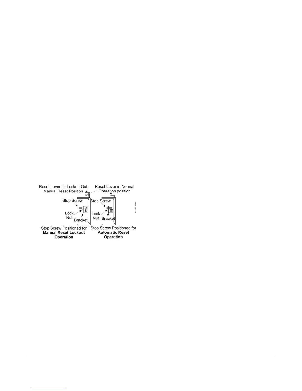 Loading...