P70, P72, and P170 Series Controls for Dual Pressure Applications Installation Instructions
11
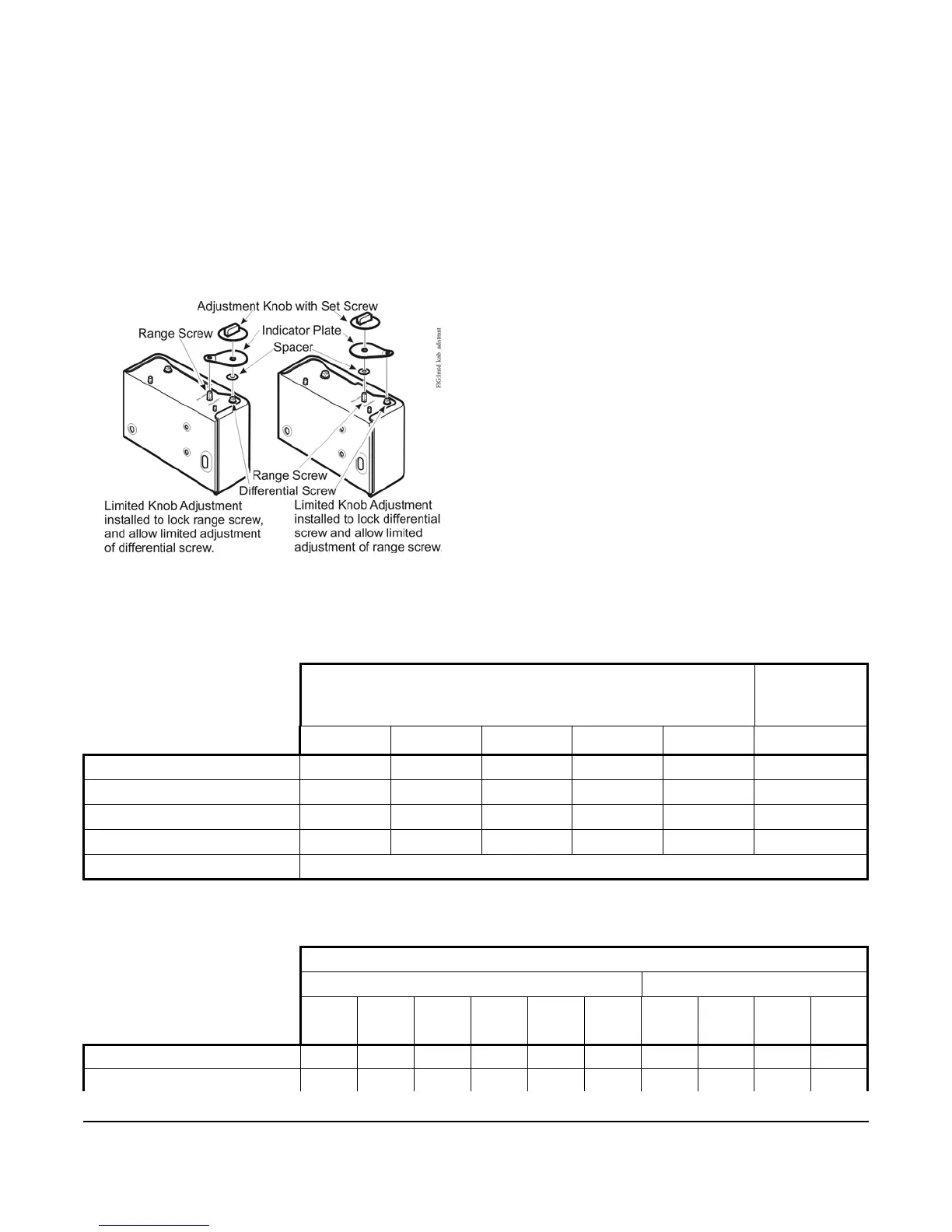
3. Place the spacer on the desired adjustment screw. All-Range controls (with Limited Knob Adjustment kits)
have round and knurled adjustment screws. The spacer must be placed on the range screw. MICRO-SET®
controls have square adjustment screws. Always place the spacer on the same adjustment screw as the knob.
4. Align the large end of the indicator plate over the adjustment screw with spacer.
5. Align the small end of the indicator plate over the adjustment screw to be locked.
6. Align the knob over the large end of the indicator plate.
7. Attach the knob to the adjustment screw, and tighten the set screw.
Note: The Limited Knob Adjustment kit for the All-Range controls cannot be used with the MICRO-SET® controls
(and vice-versa).
Technical Specifications
Table 4: SPST Electrical Ratings (P70L, M, N, and P170L, M, N Types)
Standard Single-Phase Ratings Hermetic
Compressor
1Ø Ratings
120 VAC 208 VAC 240 VAC
480 VAC
1
1. Not for compressor motor loads.
600 VAC
1
208/240 VAC
Motor Horsepower 1.5 3 3 -- -- --
Motor Full Load Amperes 20 18.7 17 5 4.8 20
Motor Locked Rotor Amperes 120 112.2 102 30 28.8 120
Non-Inductive Amperes 22 22 22 -- -- --
Pilot Duty 125 VA at 120 to 600 VAC; 57.5 VA at 120 to 300 VDC
Table 5: 4-Wire 2-Circuit Electrical Ratings (P70P, Q, and R Types) (Part 1 of 2)
Standard Single-Phase Ratings
Line-M2 (Main Contacts) Line-M1 (Auxiliary Contacts)
120
VAC
208
VAC
240
VAC
277
VAC
480
VAC
1
600
VAC
1
120
VAC
208
VAC
240
VAC
277
VAC
Motor Full Load Amperes 16.0 9.2 8.0 -- 5 4.8 6.0 3.3 3.0 --
Motor Locked Rotor Amperes 96.0 55.2 48.0 -- 30 28.8 36.0 19.8 18.0 --
Figure 11: Limited Knob Adjustment
 Loading...