P70, P72, and P170 Series Controls for Dual Pressure Applications Installation Instructions
9
All-Range Controls (Low Side Only)
The low side of All-Range controls displays the CUT IN and CUT OUT setpoints. Turn the range screw to adjust the
cut in and cutout setpoints up or down simultaneously which maintains the set differential value. Turn the
differential screw to adjust the cutout setpoint and change the differential value.
MICRO-SET® Controls (Low Side Only)
The low side of MICRO-SET® controls feature a scale plate that displays the CUT IN setpoint and DIFFERENTIAL
setting. Turn the range screw to adjust the cut in setpoint. Turn the differential screw to adjust DIFFERENTIAL
setting. (This changes the cutout pressure.)
Dual Pressure Controls (High Side)
The high side scaleplate of the P70, P72, and P170 dual pressure controls displays only the CUT OUT setpoint.
Turn the range screw to adjust the cutout setpoint. The differential is fixed at about 65 psi.
For controls with Manual Reset Lockout option, see Manual Reset Operation
. For P70S and P170S controls, see
Convertible High Pressure Reset Mechanism on P70S and P170S Controls
.
To adjust the dual pressure controls:
1. Set the low side cut in setpoint by adjusting the low side range screw.
All-Range Controls: Turn the screw clockwise to raise the cut in setpoint.
MICRO-SET Controls: Turn the screw clockwise to lower the cut in setpoint.
2. Adjust the differential screw.
All-Range Controls: Turn the screw clockwise to raise the cut out setpoint.
MICRO-SET® Controls: Turn the screw clockwise to increase the differential value.
3. Set the high side cutout setpoint by adjusting the high side range screw. Turn the screw clockwise to raise the
cutout setpoint. (The high side differential is fixed.)
4. Set the reset operation (on P70S and P170S models only) for high side automatic reset or manual reset
lockout. See Convertible High Pressure Reset Mechanism on P70S and P170S Controls
and Figure 9
.
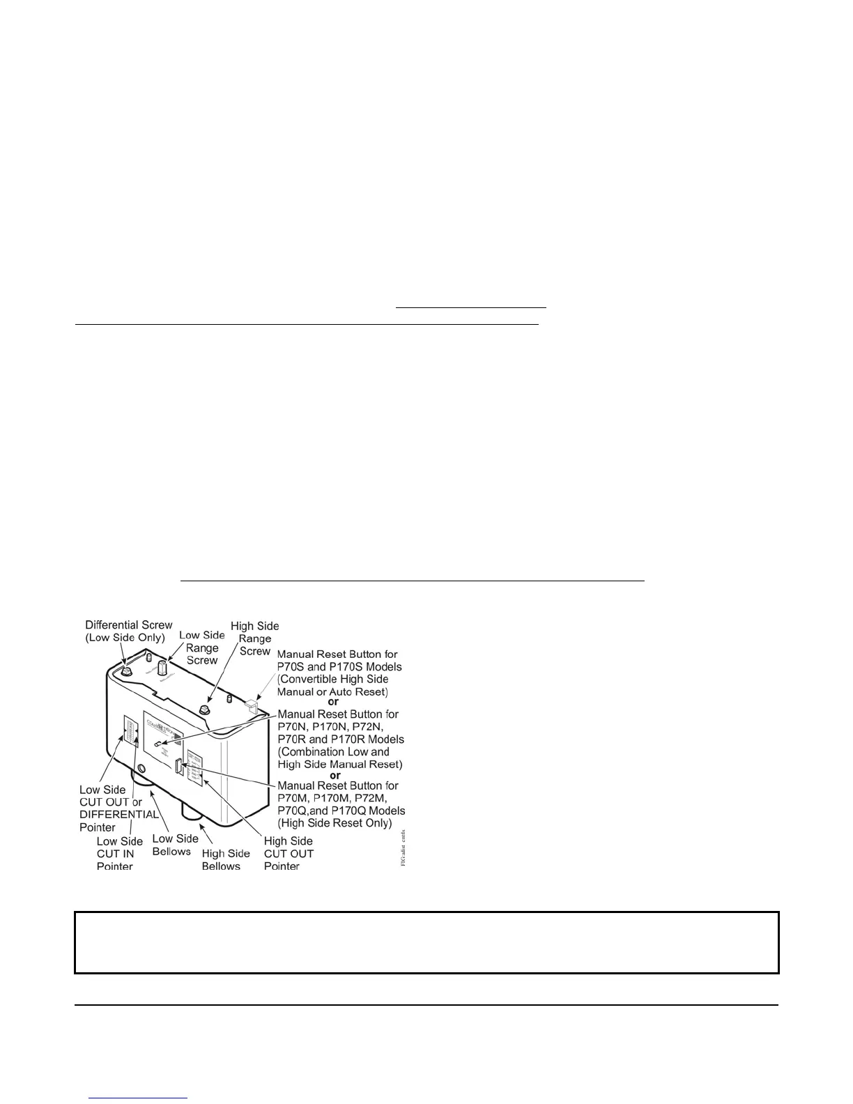
IMPORTANT: Do not adjust pointers beyond the highest or lowest indicator marks on the control’s pressure
scale. Adjusting pointers beyond indicator marks may damage screw threads, may cause inaccurate control
operation, and will void the warranty.
Figure 9: Adjusting the Dual Pressure Controls

 Loading...