P70, P72, and P170 Series Controls for Dual Pressure Applications Installation Instructions
6
Wiring
P70, P72, and P170 controls for dual pressure applications are available with several switch options and electrical
ratings. Check the label inside the control cover for model number, switch action, and electrical rating. Check the
wiring terminal designations on the control switch block, and see the following guidelines and applicable wiring
diagrams, when wiring the control. See Table 1 through Table 3 for switch actions and models. See Technical
Specifications.
WARNING: Risk of Electric Shock.
Disconnect or isolate all power supplies before making electrical connections. More than one disconnect
or isolation may be required to completely de-energize equipment. Contact with components carrying
hazardous voltage can cause electric shock and may result in severe personal injury or death.
IMPORTANT: Use copper conductors only. Make all wiring connections in accordance with local, national, and
regional regulations. Do not exceed the P70, P72, or P170 Pressure Control electrical ratings.
IMPORTANT: Use terminal screws furnished in the switch block. Using other terminal screws will void the
warranty and may damage the switch.
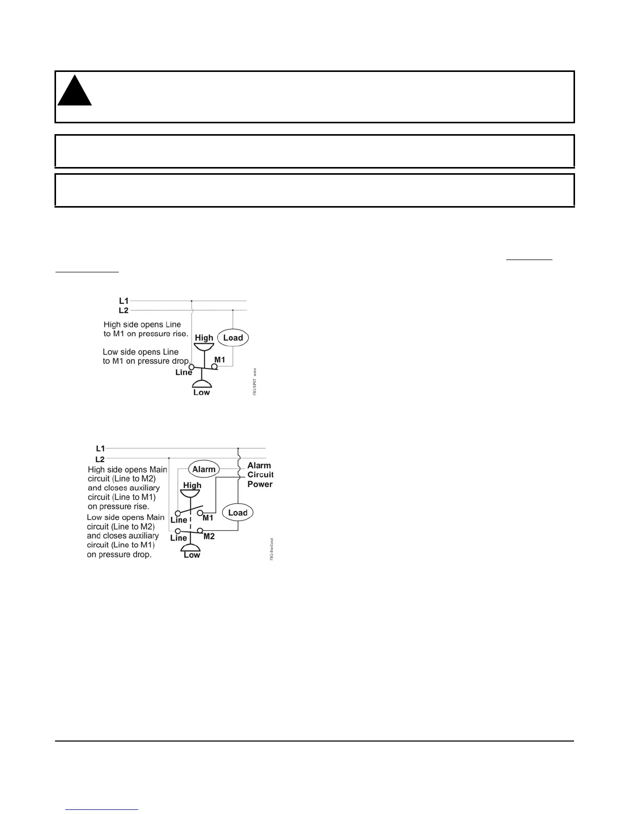
Figure 4: Typical Wiring for SPST Switch
(P70L, M, N, and P170L, M, N Models)
Figure 5: Typical Wiring for 4-Wire, 2-Circuit
Switch (P70P, Q and R Models)
 Loading...