P70, P72, and P170 Series Controls for Dual Pressure Applications Installation Instructions
3
Installation
Dimensions
See Figure 1 and Figure 2 for dimensional information.
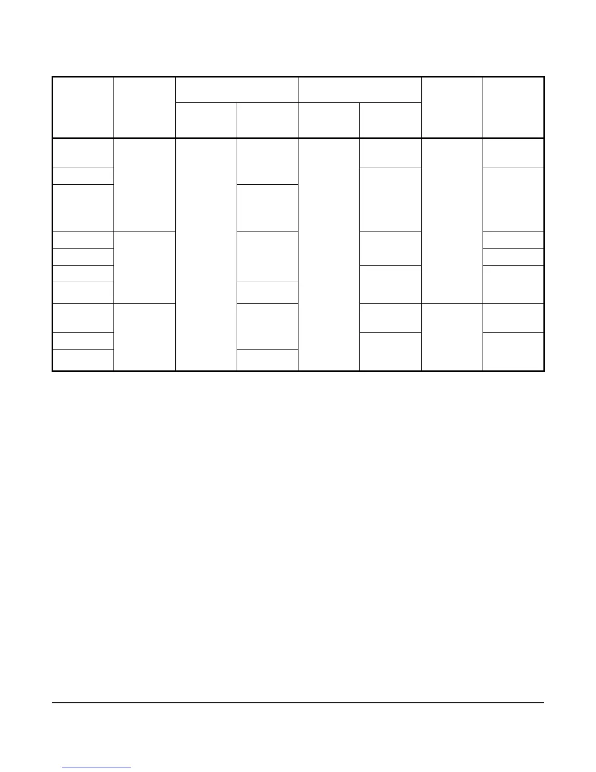
Table 3: Standard Model P70, P72, and P170 All Range Dual Pressure Controls for Non-Corrosive
Refrigerants
Model Code
Number
Switch
Action
Low Pressure Side
psig (kPa)
High Pressure Side
psig (kPa)
Pressure
Connector
Limited
Knob
Adjustment
Range Differential Range Differential
(Non-
Adjustable)
P70LB-1
1
SPST 20 in. Hg to
100 psig
(-68 to 690)
Min 6 (41)
Max 50 (345)
100 to 500
(690 to 3,447)
Fixed
Approximately
65 (448)
36 in. Capillary
with 1/4 in.
Flare Nut
Low CUT OUT
P70MA-1
1
Lockout
Requires
Manual Reset
None
P70NA-1
Fixed (Manual
Reset)
P72LA-1
1
DPST Min 7 (48)
Max 50 (345)
Fixed
Approximately
65 (448)
None
P72LB-1
1
Low CUT OUT
P72MA-1
1
Lockout
Requires
Manual Reset
None
P72NA-1
1
Fixed (Manual
Reset)
P170LB-1
1
SPST Min 7 (48)
Max 50 (345)
Fixed
Approximately
65 (448)
1/4 in. Male
Flare
Connector
Low CUT OUT
P170MA-1
1
Lockout
Requires
Manual Reset
None
P170NA-1
Fixed (Manual
Reset)
1. Control models with high pressure side (only) that are UL Listed as Refrigeration Pressure Limiting Controls.
 Loading...