VERTICAL MULTISTAGE PUMPS
10
7. Switch on the power supply and recheck the direction of
motor rotation.
STARTING.
1. If a suction line isolation valve has been installed, check to
be sure that it is completely opened.
2. For initial starting, the isolation valve in the discharge pipe
should be almost closed.
3. Start the pump.
4. When the piping system has been filled with liquid, slowly
open the discharge isolation valve until it is completely
open. Opening the valve too fast may result in water hammer
in the discharge pipe. If the pump or system starts to rattle,
the pump is cavitating; to avoid damage to the pump, reduce
the flow through the discharge isolation valve until the
rattling stops. If this does not give adequate flow for your
installation, call your installer or system designer.
5. Record the voltage and amperage of the motor. Adjust the
motor overloads if required.
6. If pressure gauges have been installed, check and record
operating pressures.
7. Check all controls for proper operation.
MOTOR BEARINGS. For the greasing schedule and greasing
procedure of the motor bearings, follow the motor manufacturer’s
recommendations.
CALCULATING MINIMUM INLET PRESSURE. Minimum
inlet pressure is required to avoid cavitation in the pump and is
calculated as follows:
H = Pb - NPSHR - H
f
- H
v
- H
s
H = Minimum inlet pressure in ft. of head
Pb = Barometric pressure in ft.
1 Bar = 29.53 inches of mercury (Hg)
1 PSI = 2.31 ft. of head
1 Bar = 33.5 ft. of head
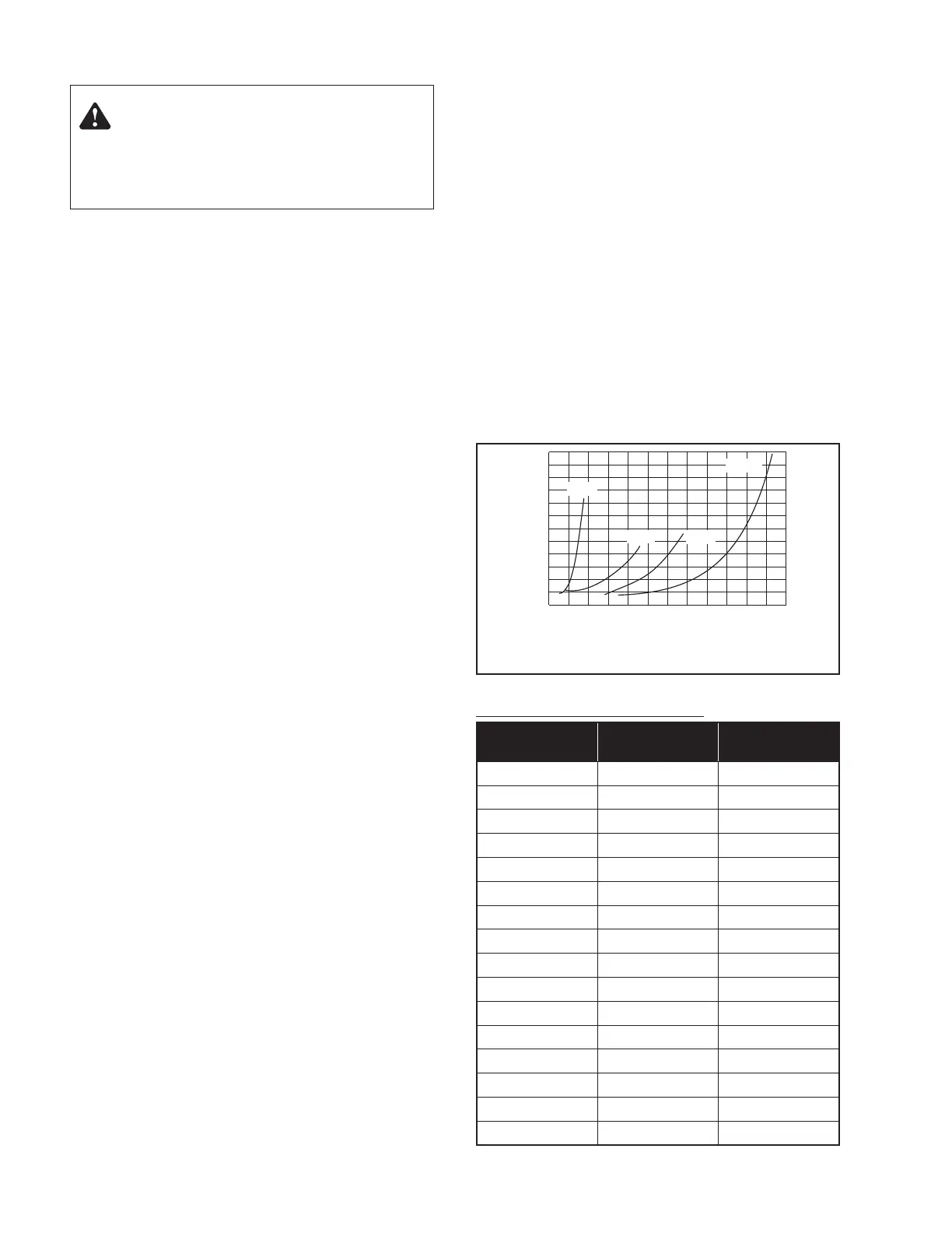
NPSHR = Net positive suction head required. To be read from
the NPSHR curve, Figure 9, at the highest flow the pump will
be delivering.
H
f
= Friction loss in suction pipe in ft. of head
H
v
= Vapor pressure in ft. of head (see Table VI)
H
s
= A safety margin of 1.64 ft. of head
Example for PVM8:
If: Flow = 60 GPM
Pb = 1 Bar = 29.53 inches of mercury*
(Convert from Bar to ft. of head)
1 inch of mercury = 1.13 ft. of water
T = 100° F
NPSHR = 10' (see Figure 9)
H
f
= 10' of 2" steel pipe @ 11.9' of loss per
100' of pipe (H
f
= 11.9'/10' = 1.19')
H
v
= 2.195' (from Table VI)
H
s
= 1.64' (safety factor from above)
Then: H = 33.5'* - NPSHR** - H
f
- H
v
- H
s
H = 33.5' - 10' - 1.19' - 2.195' - 1.64 = 18.475'
H = 18.475' = minimum inlet pressure
* 1 Bar = 14.5 PSI x 2.31 ft. of head = 33.5'
TABLE VI – Vapor Pressure of Water
Temperature in °F
(°C)
Vapor Pressure in
PSIA (kPa)
Absolute Pressure in
Feet (m) of Water
32 (0)
0.089 (.61) 0.205 (.062)
40 (4.4) 0.122 (.84) 0.281 (.086)
60 (15.6) 0.256 (1.77) 0.592 (.180)
80 (26.7) 0.507 (3å50) 1.172 (.358)
100 (37.8) 0.95 (6.55) 2.195 (.669)
120 (48.9) 1.695 (11.69) 3.914 (1.193)
140 (60.0) 2.892 (19.94) 6.681 (2.036)
160 (71.1) 4.745 (32.72) 10.961 (3.341)
180 (82.2) 7.515 (51.84) 17.36 (5.291)
200 (93.3) 11.529 (79.49) 26.632 (8.117)
210 (98.9) 14.125 (97.39) 32.629 (9.945)
212 (100)
14.698 (101.34) 33.952 (10.349)
220 (104.4) 17.188 (118.51) 39.704 (12.102)
230 (110.0) 20.78 (143.28) 48.002 (14.631)
240 (115.6) 24.97 (172.17) 57.681 (17.581)
248 (120.0)
28.79 (188.51) 66.505 (20.271)
5
10
15
20
30
25
0102030405060708090 100 110 120
NPSHR in Feet
Flow in GPM
PVM 16
PVM 8
PVM 4
PVM 2
Figure 9. PVM2 through PVM16 net positive suction head
requirement (NPSHR).
Warning: Hazardous Voltage
Voltage can shock, burn, or cause death. Ground pump motor
correctly before connecting to power supply, per article 250-
80 of the National Electrical Code (NEC) in the U.S., or the
Canadian Electrical Code (CEC), as applicable.

 Loading...


