VERTICAL MULTISTAGE PUMPS
7
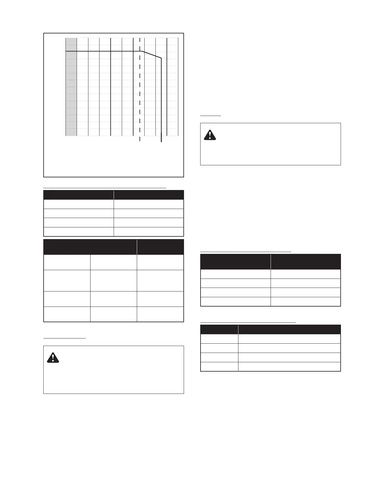
TABLE III – Permissible Operating Pressure Curves
Curve 1 Curve 2
PVM2-30/2 to PVM2-120 PVM2-150 to PVM2-180
PVM4-20/1 to PVM4-120 PVM4-140 to PVM4-160
PVM8-20/1 to PVM8-120 PVM8-140 to PVM8-160
PVM16-30/2 to PVM16-80 PVM16-100 to PVM16-120
Model Number
Maximum Inlet
Pressure (PSI)
PVM2
30/2 - 60
70 - 180
145
220
PVM4
20/1 - 20
30 - 80/7
80 - 160
90
145
220
PVM8
20/1 - 40
50 - 160
90
145
PVM16
30/2 - 30
40 - 120
90
145
INSTALLATION:
LOCATION. Locate pump in a dry, well ventilated area, not
subject to freezing or extreme variations in temperature.
Mount pump a minimum of 6" from any obstruction or hot
surface. Install the pump with the motor shaft vertical. Make sure
that an adequate supply of cool air reaches the motor cooling fan.
Maximum ambient air temperature is 104° F (40° C).
For open systems requiring suction lift, locate the pump as close
to the water source as possible.
FOUNDATION. Foundation should be concrete or a similarly
rigid foundation to provide a secure, stable mounting base for
the pump.
Secure pump to foundation using all bolt holes. Refer to Figures
2 and 3 for bolt plate dimensions. Be sure that all four pads on
the base are properly supported.
Shim pump base to make sure that pump is level.
PIPING:
If there is any danger of the pump running against a closed
discharge valve, install a pressure relief or bypass valve in the
discharge pipe to allow for minimum liquid flow through the pump.
Minimum liquid flow through the pump is needed for cooling
and lubrication of the pump (see Table IV). Run the bypass/relief
valve and discharge pipe to a floor drain or a tank for collection.
Suction pipe should be adequately sized (see Table V) and run
as straight and as short as possible to keep friction losses to
a minimum. Pipes, valves, and fittings must have a pressure
rating equal to or greater than the maximum system pressure.
TABLE IV – Minimum Pumping Rates
Type
Liquid Temperature
+5° F to +250° F
PVM2 1 GPM
PVM4 2 GPM
PVM8 4 GPM
PVM16 8 GPM
TABLE V – Minimum Suction Pipe Sizes
Type Pipe Size
PVM2 1-1/4" Nominal Diameter, Schedule 40 Pipe
PVM4 1-1/4" Nominal Diameter, Schedule 40 Pipe
PVM8 2" Nominal Diameter, Schedule 40 Pipe
PVM16 2" Nominal Diameter, Schedule 40 Pipe
Pressure check the discharge piping as required by codes or local
regulations.
“Inlet” and “Outlet” are marked on the pump base to show the
direction of the liquid flow through the pump.
Install antivibration mountings on either side of the pump if a
minimum noise level is desired.
Figure 4. Maximum Inlet Pressure and Maximum Permissible
Operating Pressure Curves.
Warning: Hazardous Voltage
Voltage can shock, burn, or cause death. Ground pump motor
correctly before connecting to power supply, per article 250-
80 of the National Electrical Code (NEC) in the U.S., or the
Canadian Electrical Code (CEC), as applicable.
Warning: Explosion and Burn Hazard
Do not run pump with discharge valve closed; the water in
the pump may boil, with risk of explosion and steam burns
to anyone near.
0
30
60
90
120
150
180
210
240
270
300
330
360
390
420
212
0 to100 120140 160 180 200 220 240
250
260
280
Pressure in PSI
Temperature in Degrees F

 Loading...


