VERTICAL MULTISTAGE PUMPS
8
Install isolation valves in both inlet and outlet pipes near the
pump (see Figure 5). This allows for removal of pump for service
without draining the system and isolation of the pump in case of
a flooded suction condition.
If the system pressure is greater than the pump’s maximum inlet
pressure, the limits of the pump can be exceeded if the discharge
pressure backs up to the inlet side of the pump. Installation of
a check valve in the discharge pipe is recommended to prevent
this condition.
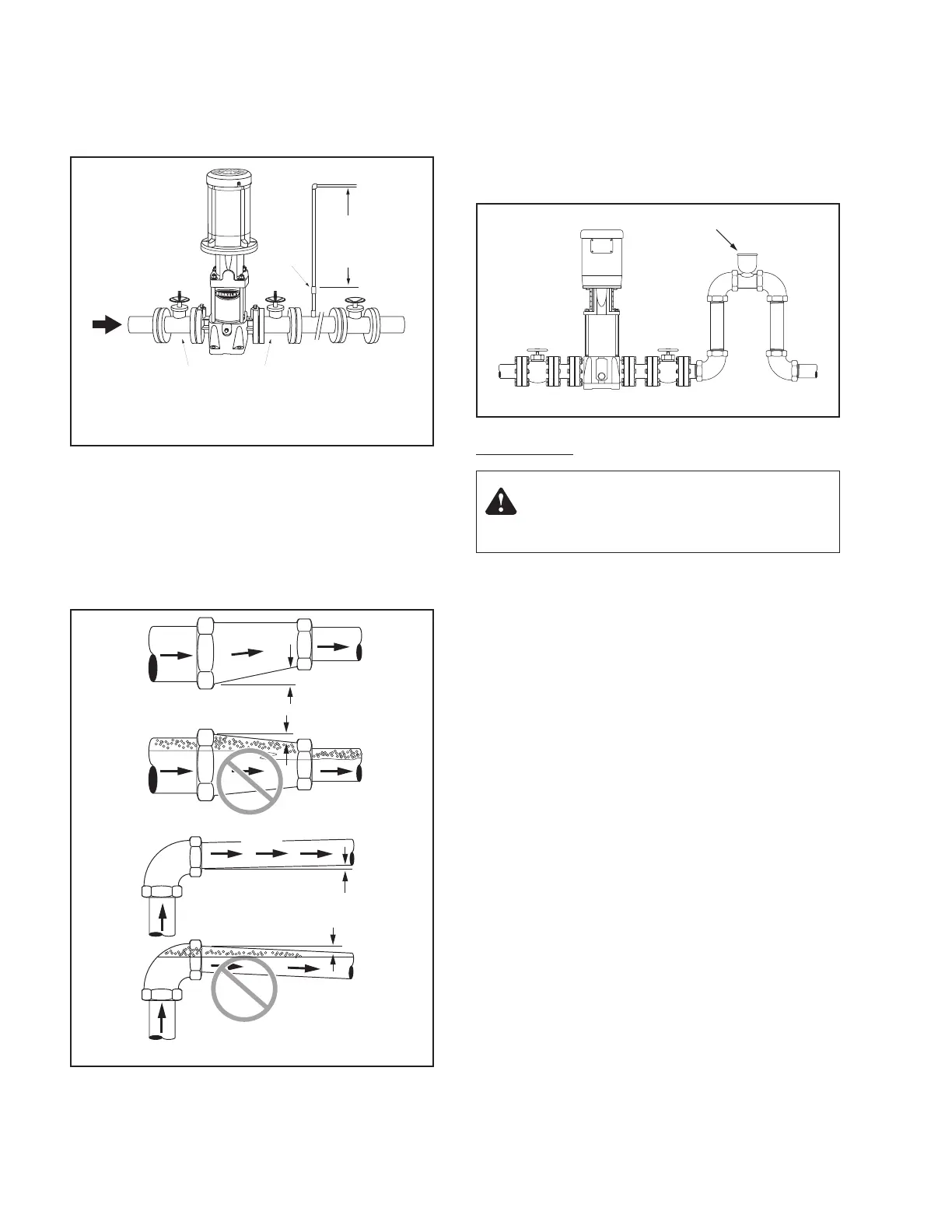
Make sure, especially on the inlet side of the pump, that there are
no airlocks in the system. See Figure 6 for correct pipe work to
avoid airlocks. The suction pipe should be level or slightly rising.
Support all piping independently of the pump so the weight
of the piping system does not strain the pump case. Make
sure that the expansion and contraction of the piping system
from temperature variations cannot put a strain on the pump.
If the system or pump must be drained periodically (especially
if the discharge pipe is horizontal or slopes downward away
from the pump), install a loop and vacuum valve as shown in
Figure 7 to protect the pump against running dry. The highest
point of the loop should be at least as high as the lowest point
of the motor. This loop/valve combination will allow the pump
and the system to be drained independently of one another.
ELECTRICAL:
All electrical work should be performed by a qualified electrician
in accordance with the National Electrical Code and all local
codes and regulations. Make sure that the motor voltage,
phase, and frequency match the incoming electrical supply. The
proper operating voltage and other electrical information can
be found on the motor nameplate. These motors are designed
to run up to ±10% of the nameplate-rated voltage. The wiring
connection diagram can be found on either a plate attached
to the motor or on a diagram inside the terminal box cover.
• If voltage variations are greater than ±10%, do not
operate the pump.
• Incorrect voltage can cause fire or serious damage to the
motor and voids warranty.
• Ground the pump motor correctly before connecting it to the
power supply.
• Follow the wiring instructions when connecting the motor to
the power lines.
POSITION OF TERMINAL BOX. To turn the motor so that the
terminal box faces the right direction, proceed as follows:
1. Disconnect the power to the pump motor.
2. Remove the coupling guards (use a screwdriver).
3. Remove the couplings.
4. Remove the bolts that fasten the motor to the pump.
5. Turn the motor to the required position (in quarter-turn
increments).
6. Follow steps 10–20 under Motor Replacement.
Figure 5. Bypass required if pump might operate with discharge
valve closed. See Table IV for minimum required flow through
pump to prevent overheating and to ensure lubrication.
Inlet
Outlet
Nipple
Orifice
Bypass Line
12" Min.
to prevent
erosion
Isolation Valves
O.K.
O.K.
Figure 6. Install pipe correctly to prevent air locks.
Warning: Hazardous Voltage
Can shock, burn, or cause death.
Vacuum Valve
Figure 7. Loop and Vacuum Valve Installation.

 Loading...


