VERTICAL MULTISTAGE PUMPS
11
MAINTENANCE:
MOTOR REPLACEMENT. For Reference Numbers [shown as
(3) or (5)], refer to the Exploded View, Figure 14, for PVM2
and PVM4 series models, Figure 16 for PVMX2 and PVMX4
models, Figure 15 for PVM8 and PVM16 series models, and
Figure 17 for PVMX8 and PVMX16 series models.
1. Disconnect the power to the pump motor.
2. Close the nearest suction and discharge valves.
3. Remove the coupling guards (4) by prying them loose with a
screwdriver.
4. Remove the socket head screws (3) and the coupling halves
(2) from the shaft (16A). For additional reference, see Figure
12.
NOTICE: Socket head screws are metric. See Table VIII for
specific metric driver sizes.
5. Remove the shaft pin (5).
6. Remove the capscrews (12), flatwashers (10), and
lockwashers (11) that hold the motor (1) and the motor
bracket (7) together.
7. Pull the old motor up and off the motor bracket. NOTICE:
Note the location of the conduit box on the motor.
8. Thoroughly clean the surfaces of the mounting flanges on
the new motor and the pump end.
9. Install the new motor on the pump with the conduit box in
the desired position.
10. Lubricate the capscrews (12) with oil.
11. Reinstall the lockwashers, flatwashers, and capscrews
that hold the motor and the motor bracket together, then
tighten evenly and diagonally. See Table VIII for torque
specifications.
12. Reinstall the shaft pin (5) in the shaft.
13. Reinstall the coupling halves (2) on the pump and motor
shaft. Make sure to engage the shaft pin (5).
NOTICE: Be sure coupling surfaces are thoroughly clean
prior to assembly.
14. Snug up the socket head screws (3) until the coupling begins
to bind and then loosen 1/2 turn.
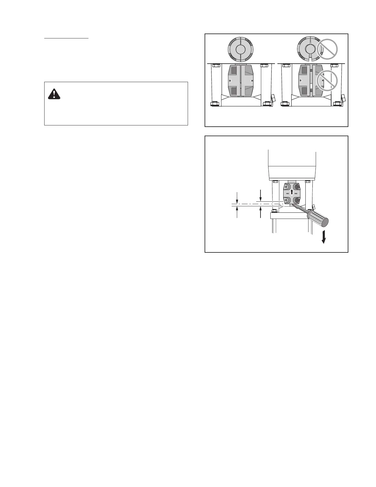
15. Draw up the capscrews evenly so the gap between the
coupling halves is equal on both sides (see Figure 10A).
16. Insert a screwdriver under the coupling (see Figure 10B).
17. Raise the pump shaft to its highest point.
18. Lower the shaft halfway back down the distance you just
raised it and retighten the capscrews. See Figure 10.
NOTICE: Torque settings are critical to prevent coupling
movement. Refer to Table VIII for torque specifications.
19. Rotate the shaft to make sure that there is no interference.
If rubbing is noted, repeat steps 16, 17, and 18 above and
readjust pump shaft height.
20. Reinstall the coupling guards by snapping them into place.
NOTICE: The guards should be in place before the unit is
run.
21. Open the suction and discharge valves. Turn the power back
on.
REPLACING PUMP STACK. For Reference Numbers [shown
as (3) or (5)], refer to the Exploded View, Figure 14 for the
PVM2 and PVM4 series models and Figure 15 for PVM8 and
PVM16 series models.
Figure 10A. Make sure that the coupling halves are
evenly tightened.
Warning: Hazardous Voltage
Disconnect all power to the pump before servicing or working
on pump. Make sure that power is locked out and that pump
cannot be accidentally started.
Motor
Pump
Raise Coupling
as far as it will go;
then tighten at
one-half the
height of total
axial play.
Axial
Play
Coupling
Setting
Figure 10B. Vertically (axial) centering the coupling.

 Loading...


