Maintenance 8
3. Fill pump and suction pipe with water.
4. Replace priming plug, using PTFE pipe thread sealant tape on thread;
tighten plug.
NOTICE: If a priming tee and plug have been provided for a long
horizontal run, be sure to fill suction pipe through this tee and replace
plug. (Don’t forget to tape the plug.)
5. Start pump: water should be produced in 10 minutes or less, the
time depending on depth to water (not more than 20') and length of
horizontal run (10' of horizontal suction pipe = 1' of vertical lift due to
friction losses in the pipe).
If no water is produced within 10 minutes, stop pump, release all
pressure, remove priming plug, refill and try again.
Hazardous pressure and risk of ex plo sion and scalding. If
pump is run con ti nu ously at no flow (that is, with discharge shut off or
without priming), water may boil in pump and piping system. Under
steam pressure, pipes may rupture, blow off of fittings or blow out of
pump ports and scald anyone near.
To prevent explosion, do the following:
A. Be sure discharge (valve, pistol grip hose nozzle, etc.) is open
whenever pump is running.
B. If pump fails to produce water when attempting to prime, release all
pressure, drain pump and refill with cold water after every two attempts.
C. When priming, monitor pump and piping tempera ture. If pump or
piping begin to feel warm to the touch, shut off pump and allow
system to cool off. Release all pressure in system and refill pump and
piping with cold water.
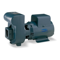
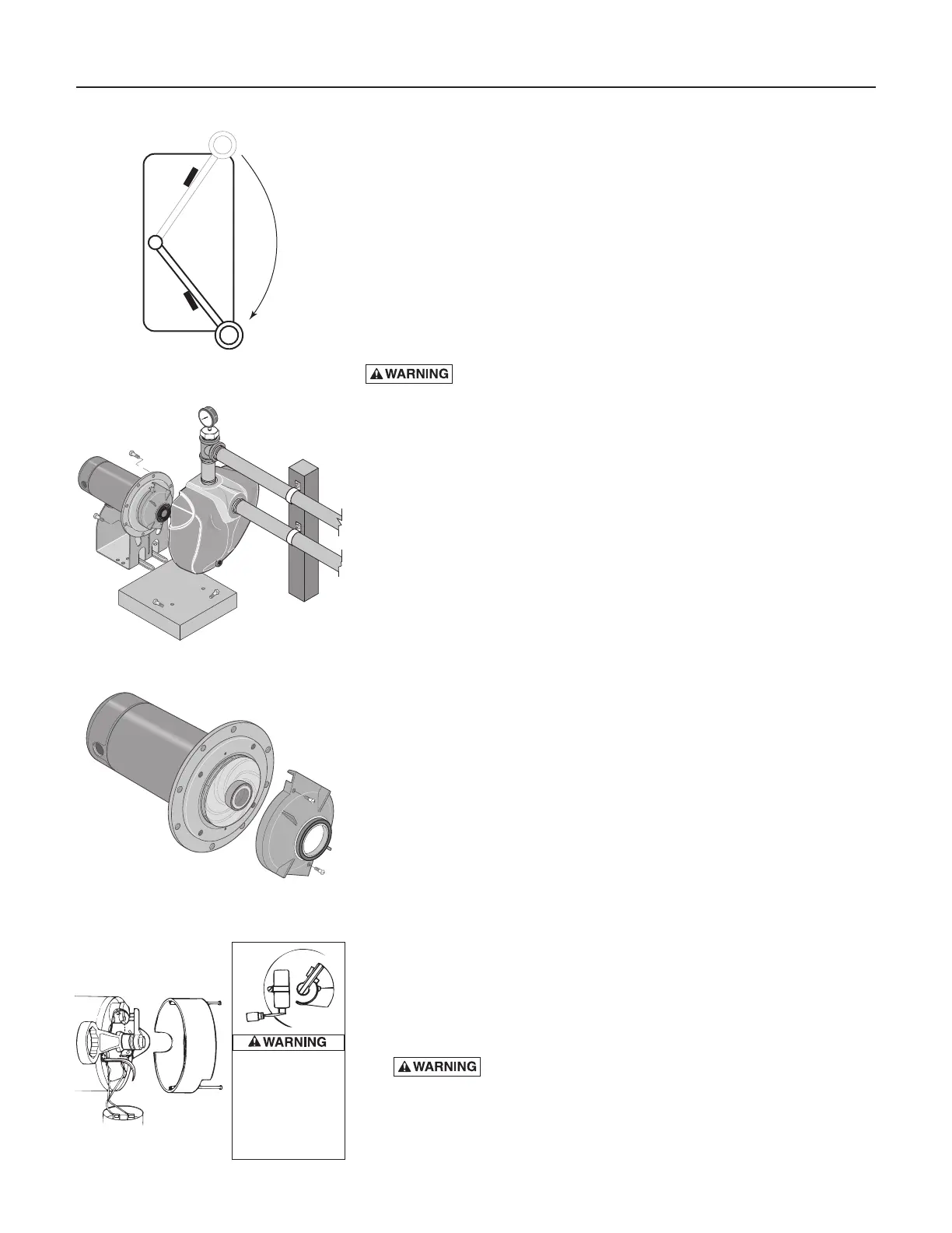
Pump and piping need not be disconnected to repair or replace motor or
seal (see Figure 13). If motor is replaced, replace the shaft seal (Key No. 5,
Page 12). Keep one on hand for future use.
Be sure to prime pump before starting.
NOTICE: Check motor label for lubrication instructions. The mechanical
shaft seal in the pump is water lubricated and self-adjusting.
NOTICE: Drain pump when disconnecting from service or when it might
freeze.
PUMP DISASSEMBLY
1. Disconnect power to motor.
NOTICE: Mark wires for correct assembly.
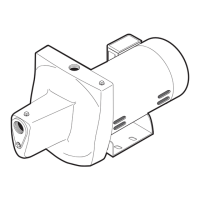
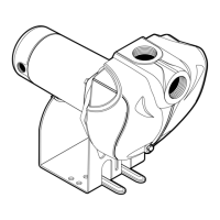
2. Remove capscrews holding seal plate to pump body. Motor assembly
and seal plate can now be pulled away from pump body (Figure 13).
CARE FULLY remove gasket.
CLEANING/REPLACING IMPELLER
NOTICE: First, follow instructions under “Pump Dis assembly”.
1. Remove screws fastening diffuser to seal plate; re move diffuser (see
Figure 14). Exposed impeller can now be cleaned.
2. If impeller must be replaced, loosen two machine screws and remove
motor canopy (see Figure 15).
3. Capacitor voltage may be hazardous. To discharge
capacitor, hold insulated handle screwdriver BY THE HANDLE and
short capacitor terminals together (see Figure 15). Do not touch
metal screwdriver blade or capacitor terminals. If in doubt, consult a
qualified electrician.
ON
OFF
Figure 12: Disconnect Power
20
100
80
60
40
Figure 13: Slide Motor Back
Figure 14: Remove Diffuser
Figure 15: Hold Shaft
To avoid electrical
shock hazard, use
insulated-handle
screwdriver to
short capacitor
terminals
as shown.