Installation 6
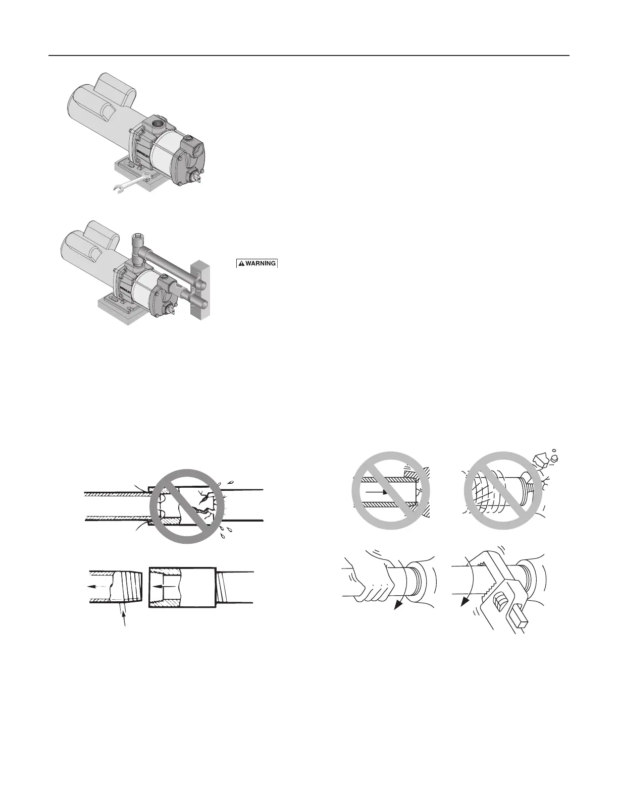
1 Bolt pump to solid, level foundation.
2. Support all piping connected to the pump.
3. Wrap1-1/2totwolayersofPTFEtapeclockwise(asyoufaceendof
pipe) on all male threads being attached to pump.
4. Tighten joints hand tight plus 1-1/2 turns. Do not overtighten.
NOTICE : Installpumpasclosetowellheadaspossible.Longpipingruns
and many fittings create friction and reduce flow.
NOTICE: For long horizontal pipe runs, install a priming tee between check
valve and well head as shown in Figure 6. For driven point installations,
install a check valve as shown in Figure 6. Be sure check valve flow arrow
points toward pump.
Useschedule80orironpipe.SeeWell Pipe In stalla tion for more
information.
Wiring
Hazardous voltage. Follow these rules to avoid potential harm:
• Groundmotorbeforeconnectingtoelectricalpowersupply.Failureto
ground motor can cause severe or fatal electrical shock hazard.
• Donotgroundtoagassupplyline.
• Toavoiddangerousorfatalelectricalshock,turnOFFpowertomotor
before working on electrical connections.
• Supplyvoltagemustbewithin±10%ofnameplatevoltage.Incorrect
voltagecancausefireordamagemotorandvoidswarranty.Ifindoubt
consult a licensed electrician.
• UsewiresizespecifiedinWiring Chart.Ifpossible,connectpumptoa
separate branch circuit with no other appliances on it.
• Wiremotorasshown(Figure12B).Ifmotornameplatediagramdoes
not match either Figure 12A or 12B, follow nameplate diagram.
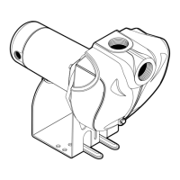
Figure 8 – Bolt Pump Down
4322 0203
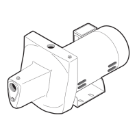
Figure 9 – Independently Support All
Piping Attached to Pump
4323 0203
Figure 10 – Use PTFE pipe thread sealant tape on pipe
joints and connections to pump.
Suction pipe.
If air flows
water won’t
Use PTFE tape.
Use PTFE pipe thread sealant tape or pipe joint
compound approved for use on PVC.
Figure 11 – Don’t overtighten.
Don’t Hit
Thread Stops
Overtighten
rom
Well
Pump
Body
Hand Tight Plus 1-1/2 Turns With Wrench.