Electrical 7
Connection Diagram for Single-Phase Motors
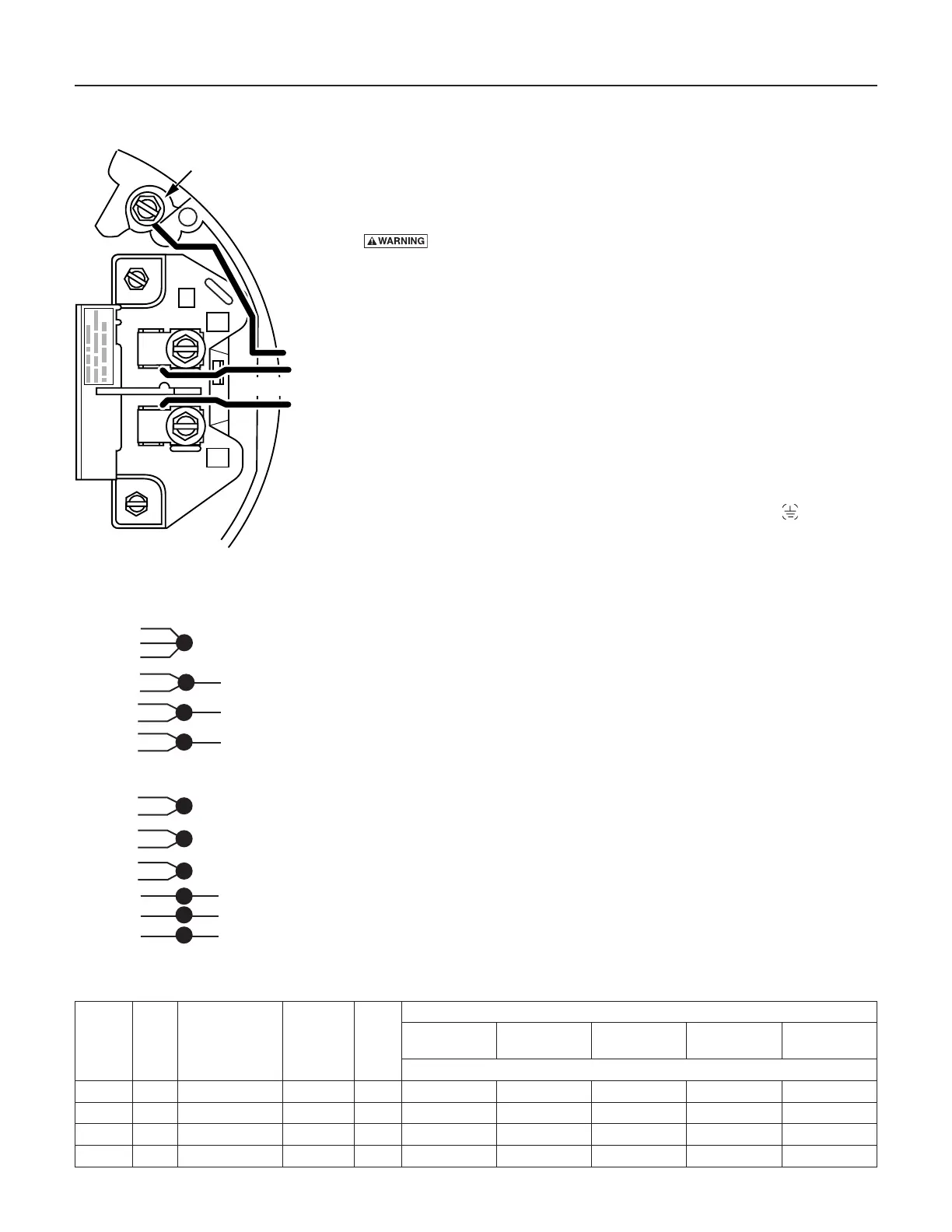
Yourmotor’sterminalboard(underthemotorendcover)shouldmatchthe
diagram in Figure 12A or 12B.
For single-phase motors, follow Figure 12A. For 3-phase motors, follow
Figure12B.Ifmotordoesnotmatchthispicture,followtheconnection
diagram on the motor nameplate or in the motor connection box.
Hazardous voltage. Can shock, burn, or cause death. Disconnect
powertomotorbeforeworkingonpumpormotor.Groundmotorbefore
con necting to power supply.
1. Install,ground,wireandmaintainthispumpinaccordancewith
electrical code requirements. Consult your local building inspector for
information about codes.
2. Provide a correctly fused disconnect switch for protection while
working on motor. Consult local or national electrical codes for
switchrequirements.
3. Disconnectpowerbeforeservicingmotororpump.Ifthedisconnect
switch is out of sight of pump, lock it open and tag it to prevent
unexpected power appli cation.
4. Groundthepumppermanentlyusingawireofthesamesizeasthat
specifiedinwiringchart(below).Makegroundconnectiontogreen
groundingterminalundermotorcanopymarkedGRD.or .
5. Connect ground wire to a grounded lead in the service panel or to a
metal underground water pipe or well casing at least 10 feet long. Do
not connect to plastic pipe or insulated fittings.
6. Protect current carrying and grounding conductors from cuts, grease,
heat, oil, and chemicals.
7. ConnectcurrentcarryingconductorstoterminalsL1andL2under
motor canopy (single phase) or in motor connection box (3-phase).
When replacing motor, check wiring diagram on motor nameplate
againstFigures12Aand12B.Ifthemotorwiringdiagramdoesnot
match one of the diagrams in Figures 12A and 12B, follow the dia gram
on the motor.
8. Motorhasautomaticinternalthermaloverloadprotection.Ifmotorhas
stopped for unknown reasons, thermal overload may restart it unex-
pectedly, which could cause injury or property damage. Disconnect
power before servicing motor.
9. Ifthisprocedureorthewiringdiagramisconfusing,consulta
licensedelectrician.
A
L2
L1
230 V
Ground
Screw
Figure 12A – 230V Single Phase
Wiring Diagram
Wiring Chart – Recommended Wire and Fuse Sizes
Model
Motor
HP
Volts/Hz/Phase
Service
Factor Amp
Branch
Fuse*
Rating
Amp
Distance In Feet(Meters) From Motor To Supply
0 - 100
(0 - 30)
101 - 200
(31 - 61)
201 - 300
(62 - 91)
301 - 400
(92 - 122)
401 - 500
(123 - 152)
AWG Wire Size (mm²)
B82456 2 230/60/1 13.3 20 12 (3) 12 (3) 10 (5.5) 10 (5.5) 8 (8.4)
B82639 2 208-230/460/60/3 10.2/5.1 15/15 14 (2)/14 (2) 14 (2)/14 (2) 12 (3)/14 (2) 10 (5.5)/14 (2) 10 (5.5)/14 (2)
B86073 2 230/60/1 9.8 20 14 (2) 14 (2) 12 (3) 10 (5.5) 10 (5.5)
B86074 2 208-230/460/60/3 9.2/4.6 15/15 14 (2)/14 (2) 14 (2)/14 (2) 12 (3)/14 (2) 10 (5.5)/14 (2) 10 (5.5)/12 (3)
* Dual element time delay fuse
3-Phase High Voltage
4-Brown
5-Orange
6-Black
1-Red
7-Purple
2-White
8-Gray
3-Blue
9-Pink
4-Brown
7-Purple
5-Orange
8-Gray
6-Black
9-Pink
1-Red
2-White
3-Blue
LINE 1
LINE 2
LINE 3
LINE 1
LINE 2
To reverse
rotation,
interchange
any two line
leads.
Figure 12B – 3-Phase Wiring Diagram