ETi 250 High Efficiency Pool and Spa Heater Installation and User’s Guide
16
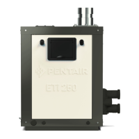
Figure 6. Ignition Control Module (ICM)
SAFETY CONTROLS (continued)
STACK FLUE SENSOR (SFS)
The heater is equipped with one Stack Flue Sensor (SFS), in the heat exchanger. The SFS monitors the stack ue
temperature and if needed will shut down the heater if the stack ue temperature exceeds 170° F (77° C). For more
information see page 57, Error Fault Code (ERR SFS).
THERMAL FUSE
A Thermal Fuse (TF) is a safety protection device that opens the electrical circuit if the ue gas temperature exceeded
the limit. There are two thermal fuses connected in series. One fuse controls the temperature of the heat exchanger
coils and the other controls the temperature of the ue gas leaving the heat exchanger. For more information see
page 58, Error Fault Code (ERR TF).
FLOAT SWITCH
The oat switch (CFS) is reed type oat switch. The oat activates the reed switch once the condensate level in the
exhaust exceeds the permitted level, the heater will shut down. For more information see page 58, Error Fault Code
(ERR CFS).
IGNITION CONTROL MODULE OPERATION
The Ignition Control Module, (Figure 6), is microprocessor based and operates on 24 VAC supplied by the transformer.
The control module utilizes a microprocessor to continually safely monitor, analyse, and control the proper operation of
the gas ame holder. The module with the presence of the ame sensor, using ame rectication, allows the heater to
operate.
Figure 7. Heater left side panel
Operation Instructions
ETi 250 ICM
IND
FENWALL
TH
VAL
NC
F2
L1
B.
Diagnostic errors are displayed on
the control panel LCD: PS, HLS, SFS,
AFS, AGS, IGN, or NONE.
See Troubleshooting (page 52-57)
Flame Current
Check Point
Figure 37.
Displayed Message Description
CONTROL FAULT Displays Message on Automation System
AIR FLOW FAULT Displays Message on Automation System
FLAME NO CALL FOR HEAT Displays Message on Automation System
IGNITION LOCKOUT Displays Message on Automation System
WEAK FLAME Displays Message on Automation System
and viewed on Heater menu
GOOD FLAME Displays Message on Automation System
and viewed on Heater menu
Diagnostic Indicator
 Loading...