ETi 250 High Efficiency Pool and Spa Heater Installation and User’s Guide
17
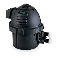
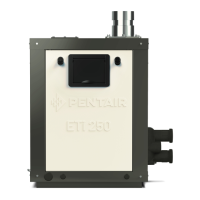
HEATER DESCRIPTION
The ETi
®
250 Heater has precisely matched orice plates to meter the air and gas into the mixer. The blower draws the air
and gas through the mixer and forces it into the burner’s ame holder. A sealed TitanTough™ Heat Exchanger surrounds the
ame holder, discharging exhaust gases out the ue (See Figure 8 and 9). Use a 2-in (5.08 cm) tting to connect to the
2-in (5.08 cm) PVC slip unions provided with the heater. The outer manifold remains cool; no heat sinks are required.
The heater operator control panel is located on the side of the heater. For ETi 250 Heater replacement parts, see page 66.
Installation Instructions
Pentair strongly recommends that all vents, pipes and exhaust systems be initially and periodically tested for proper
operation. This testing can be accomplished by using a hand-held carbon monoxide meter and/or by consult-
ing with a gas professional. Pool and spa heaters must be used in conjunction with carbon monoxide detectors
installed near the pool heater. The carbon monoxide detectors must be periodically inspected for proper operation so
as to insure continued safety. Broken or malfunctioning carbon monoxide detectors must be replaced immediately.
Figure 8. ETi 250 Heater (Left Side View)
Figure 9. ETi 250 Heater (Right Side View)
Electrical
and Bonding lug
Blower
Heat
Exchanger
Vent Cap
CPVC Flue
Outlet
Exhaust
Assembly
Tridicator (Water
pressure and
Temperature gauge)
High-Limit
Switch (HLS)
Auto gas
shut-off switch
(AGS)
Condensate Neutralizer
Cartridge
(Optional, P/N 476375
sold separately).
The cartridge may be
mounted onto the heater
base for heater outdoor
installation.
THIS HEATER MUST BE INSTALLED AND SERVICED BY A PROFESSIONAL SERVICE TECHNICIAN,
QUALIFIED IN POOL HEATER INSTALLATION.
Tubing for
Condensate
Neutralizer
Cartridge
Heater Base (Top View)
To drain
To drain
2-in Outlet
Plumbing
Installation
2-in Inlet
Plumbing
11
12
13
6
14
11
12
13
14
Ignition Control
Module (ICM)
GAS
CONTROL
VALV E
Condensate Neutralizer
Cartridge
 Loading...