ETi 250 High Efficiency Pool and Spa Heater Installation and User’s Guide
30
INDOOR VENTING — General Requirements
The heater must be installed as a Category IV appliance.
Vented Appliance (Category IV) – Vertical or Horizontal
An appliance that operates with a positive vent static pressure and with a vent gas temperature that allows excessive
condensate production in the vent, see Figure 26 (page 32) and Figure 29, page 36.
If you are considering connecting this heater to a pre-existing vent system, make sure that the vent system meets the
appropriate venting requirements as given in this manual on page 36. If not, replace the vent system. DO NOT use a
draft hood with this heater.
The heater operates with a positive vent static pressure and with a vent gas temperature less than 170° F (77° C).
The total length of the horizontal run must not exceed the length that is listed in Table 3 on page 31.
HEATER CLEARANCES — General Requirements
INDOOR INSTALLATION OR OUTDOOR SHELTER (US AND CANADA)
The following clearances must be maintained from combustible surfaces:
TOP .................................... 6 in (15 cm)
EXHAUST SIDE ................. 6 in (15 cm)
HEADER SIDE ................... 6 in (15 cm)
DOOR PANELS (*) ............ 6 in (15 cm)
NOTE: (*) For service access it is advisable to allow for sufcient clearance on at least one door panel. The heater is
design certied by CSA International for installation on combustible ooring. For installation on carpeting, the heater
must be mounted on a metal or wood panel that extends at least 3 in (10 cm) beyond the base of the heater. If the
heater is installed in a closet or alcove, the entire oor shall be covered by the panel. For an outdoor shelter installation,
the exhaust must discharge into a vent pipe. Orient the heater so that the vent pipe does not interfere with adjustment
of the operator control panel.
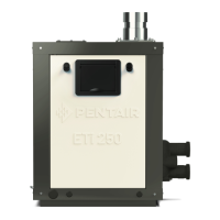
DIRECT AIR INTAKE COVER
The heater is supplied from the factory with a cover on the top
panel for outdoor installation (see Figure 25).
Remove the outside air intake cover for outdoor shelter installation
or Indoor Installation.
6 in
(15 cm)
6 in
(15 cm)
6 in
(15 cm)
6 in
(15 cm)
Operator
control
panel
Inlet / outlet plumbing
Air intake cover
Figure 25.
Control Panel and Plumbing Orientation: The control panel
can be installed on three different sides of the heater for easy
access. The control panel cannot be installed on the water
manifold side of the heater.
Installation
 Loading...