
A
Alyssa BeckerAug 16, 2025
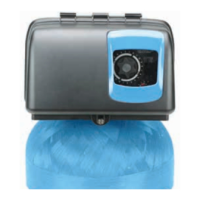
Why is my Pentair Water Filtration System using too much salt?
- PPamela TylerAug 16, 2025
Your Pentair Water Filtration System might be using too much salt due to an improper salt setting. Check the salt usage and salt setting. Another possible cause is excessive water in the brine tank; in this case, refer to the troubleshooting steps for 'Excessive water in brine tank'.